1 Before Use
Be sure to disconnect the mains cord before adjusting the voltage selector.
Use a minus(-) screwdriver to set the voltage selector (on the rear panel) to the voltage setting for the area in which the unit will
be used. (If the power supply in your area is 117V or 120V, set to the “127V” position.)
Note that this unit will be seriously damaged if this setting is not made correctly. (There is no voltage selector for some
countries, the correct voltage is already set.)
2 Before Repair and Adjustment
Disconnect AC power, discharge Power Supply Capacitors C5815~C5818, C5829~C5830, C5835~C5836 and C5841
through a 10? , 5W resistor to ground.
DO NOT SHORT-CIRCUIT DIRECTLY (with a screwdriver blade, for instance), as this may destroy solid state devices.
After repairs are completed, restore power gradually using a variac, to avoid overcurrent.
Current consumption at AC 110/127/220~230V, 50/60 Hz in NO SIGNAL at (vol. min, in CD mode) should be as below:
2.1 Rework Process for Main Board
Versión RJBX0405A-1
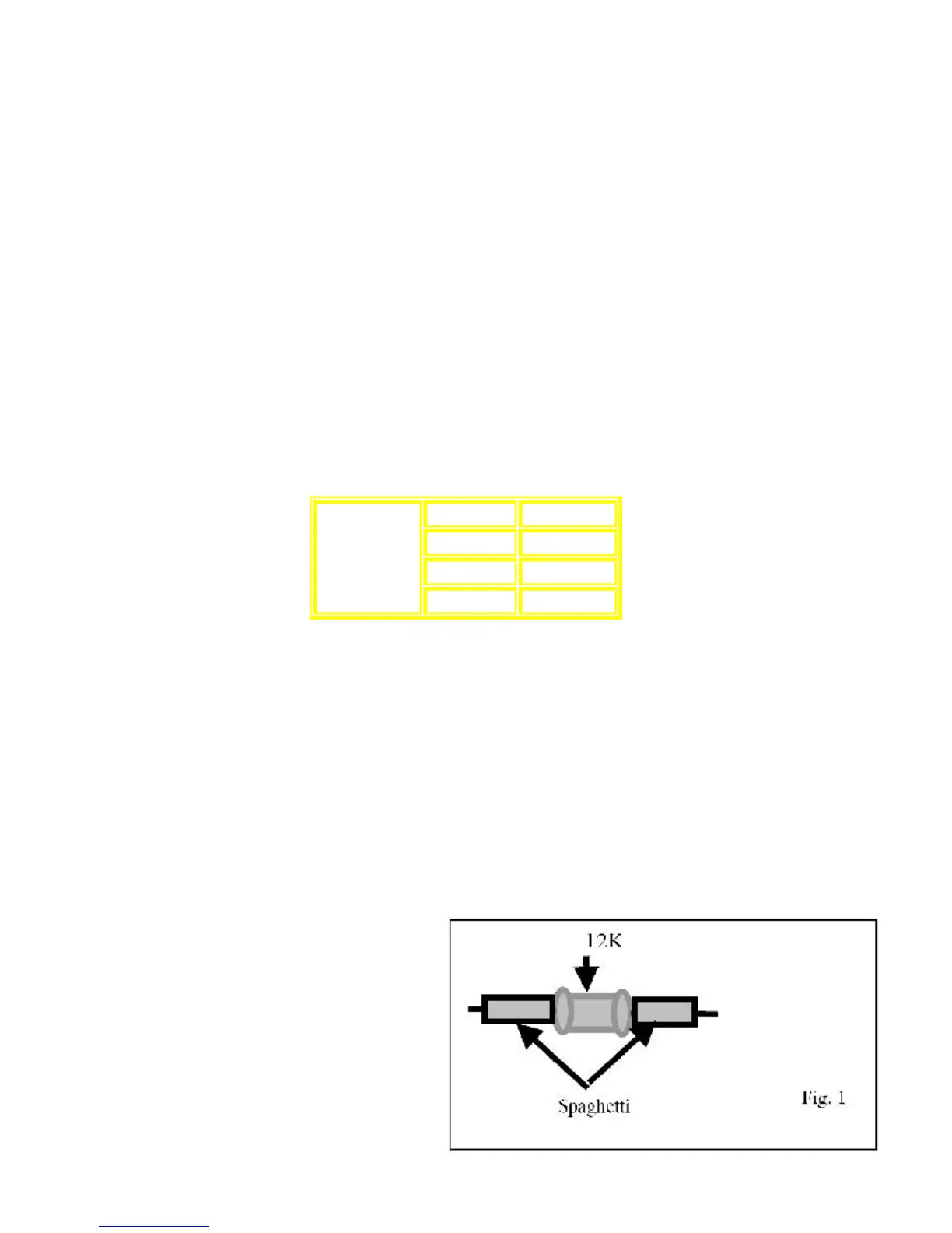
For Main PCB version 1 only (RJBX0405A-1), is necessary add two Axial resistors covered with a plastic tube in order
to countermeasure a Pop Noise during Tuner - Recording.
Be sure that during the usage of this PCB these components are included.
Material Required:
1.) 2 Axial Resistor , (ERDS2TJ123T)
2) 5 Cm Of Spaghetti , (W1VT)
3) 1g of Diabond , (DN83K)
Step1.
Prepare the axial resistors as showed in the Fig. 1
110 V ~ 1200 mA
127 V ~ 1100 mA
220-230 V ~ 700 mA
AC 50/60Hz
240 V ~ 650 mA