GB/IE/NI/CY/MT
19
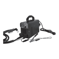
z Adaptation of device to flux-cored welding wire without inert gas
If you are using flux-cored welding wire with integrated inert gas, then you do not have to have an
external inert gas supply.
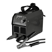
First connect the plug
32
with the connector marked with the “-”. To fix it in place, rotate in a
clockwise direction. If you are in any doubt, then please contact a professional. Connect the cable
assembly with direct connection
10
to the appropriate connector. To fix the connection, tighten the
fixing ring
38
in a clockwise direction.
Then connect the earth cable
4
with the corresponding connector, marked with the “+” and to fix
the connection in place, rotate in a clockwise direction.
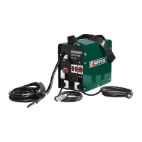
z Inserting welding wire
Unlock and open the cover of the wire feed unit
1
, by pushing the release knob upwards.
Unlock the roller unit by turning the roller mount
27
anti-clockwise (see Fig. F).
Pull the roller mount
27
off the shaft (see Fig. F).
NOTE: Make sure that the end of the wire does not come loose and cause the roll to roll out on its
own. The end of the wire may not be released until during assembly.
Completely unpack the welding wire reel
15
, so that it can unrolled without difficulty.
Do not release the wire end yet.
Place the wire reel on the shaft. Make sure that the roll unwinds on the side of the
29
wire feed guide
(see Fig. G and M).
Place the roll mount
27
back on and lock it by pressing and turning it clockwise (see Fig. G).
Undo the adjustment screw
25
and swing it downwards (see Fig. H).
Turn the thrust roller unit
26
to the side (see Fig. I).
Loosen the feed roll holder
28
by turning it anti-clockwise and pull it forwards and off (see Fig. J).
On the top of the feed roll
18
, check whether the appropriate wire thickness is indicated.
If necessary, the feed roll
18
has to be turned over or replaced (see Fig. N). The supplied welding
wire (Ø 1.0 mm) must be used in the feed roll
18
with the specified wire thickness of Ø 1.0mm.
The welding wire must be positioned in the upper groove!
Erect the feed roll holder
28
again and screw clockwise direction.
Remove the torch nozzle
7
by pulling and turning it clockwise (see Fig. K).
Unscrew the welding
14
nozzle (see Fig. K).
Guide the cable assembly with direct connection
10
away from the welding device as straight as
possible (place it on the floor).
Take the wire end out of the edge of the spool (see Fig. L).
Trim the wire end with wire scissors or a diagonal cutter in order to remove the damaged, bent ends
of the wire (see Fig. L).
NOTE: The welding wire must be kept under tension the entire time in order to avoid a releasing
and a roll out! Therefore it is recommended to carry out the work with an additional person.
Push the welding wire through the wire feed guide
29
(see Fig. M).
Guide the welding wire along the feed roll
18
and push it into the cable assembly holder
30
(see Fig. N).
Swivel the thrust roller unit
26
towards the feed roll
18
(see Fig. O).
Mount the adjustment
25
screw (see Fig. O).
Set the counter pressure with the adjustment screw
25
. The welding wire must be firmly positioned
between the thrust roller and feed roll
18
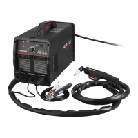
in the upper guide without being crushed (see Fig. O).
Switch on the welding device on the main
5
switch (see Fig. A).
Press the torch button
9
.
 Loading...