20
GB/IE/NI/CY/MT
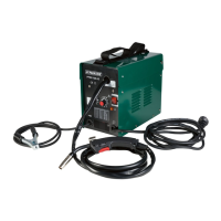
Now the wire feed system pushes the welding wire through the cable assembly
10
and the torch
8
.
As soon as 1–2 cm of the welding wire protrudes from the torch neck
31
, release the torch button
9
again (see Fig. P).
Switch off the welding device on the main switch.
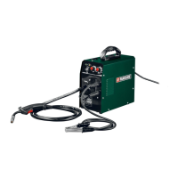
Screw the welding nozzle
14
back on. Make sure that the welding nozzle
14
matches the diameter
of the welding wire used (see Fig. Q). With the welding wire delivered with the product, the welding
nozzle
14
with the labelling 1.0 or 1.0 A must be used when using solid aluminium wire.
Push the torch nozzle
7
back on to the torch neck with a turn to the right
31
(see Fig. R).
Always unplug the mains plug from the socket prior to each maintenance
task or preparatory work in order to prevent the risk of an electric shock, injury or damage.
z Using the device
z Switching the device on and off
Switch the welder on and off on the main
5
switch. If you do not intend to use the welder for an
extended period, remove the plug from the power socket. This is the only way to completely de-energise
the device.
z Selecting the welding method
First set the welding mode by pressing the welding mode selector key
35
. You can choose between Al
(aluminium welding), MIG, MAG and FLUX (flux-cored wire). You can then set the current and voltage
using the
6
and
36
rotary switches. You can select the SYN mode for aluminium wire as well as 0.8 mm
solid wire and 1.0 mm flux-cored wire. In this mode the voltage and current are already synchronised.
This is particularly recommended for inexperienced users. In order to activate SYN, first select the
required welding mode and then keep the welding mode selector key
35
pressed for approx. 2 seconds.
In all cases, the optimum welding settings should be determined by welding on a sample workpiece.
z Welding
Overload protection
The welder is protected against overheating by means of an automatic protection device (thermostat with
automatic restart). The protective device breaks the electrical circuit if overheating occurs.
The O.H. display
37
lights up.
Allow the device to cool down for the activation of the protection device. After approx.
15 minutes, the device is ready to be used again.
Overcurrent indicator
In the event of misuse, the output current may exceed the intended maximum value. In this case, the
protective device breaks the welding current circuit and the “O.C” overcurrent indicator is shown on the
display. If the overcurrent indicator is shown, switch the device off using the main switch
5
.
After approx. 15 minutes, the device is ready to be used again and can be switched on using the main
switch
5
.
 Loading...