(Table 117, contd)
Troubleshooting Test Steps
Values Results
8. Check the Wires for Damage to the Insulation
A. Carefully inspect each wire for signs of abrasion, nicks, and
cuts. Inspect the wires for the following conditions:
• Exposed insulation
• Rubbing of a wire against the engine
• Rubbing of a wire against a sharp edge
B. Check all the fasteners for the harness and the strain relief
components on the ECM to verify that the harness is correctly se-
cured. Also check all the fasteners to verify that the harness is not
compressed. Pull back the harness sleeves to check for a flat-
tened portion of wire. A fastener that has been overtightened flat-
tens the harness. This condition damages the wires that are inside
the harness.
Wire Insulation Result: There is damage to the harness.
Repair: Replace the harness. Use the electronic service
tool to clear all logged diagnostic codes and then verify
that the repair eliminates the fault.
Proceed to Test Step 9.
Result: The wires are free of abrasion, nicks, and cuts
and the harness is correctly clamped.
Proceed to Test Step 9.
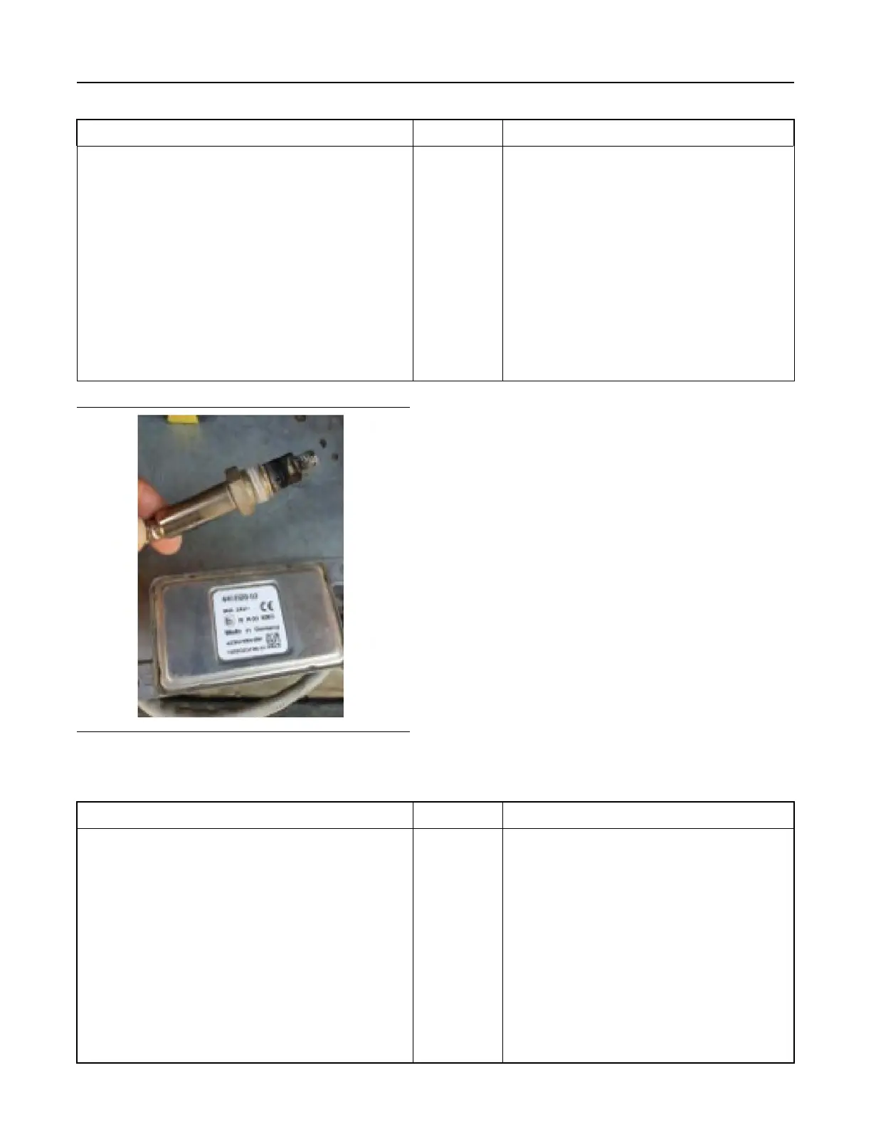
Illustration 78 g06550819
Typical view of a NOx sensor and control module
Table 118
Troubleshooting Test Steps
Values Results
9. Inspect the Inlet and Outlet NOx Sensors and the Ammonia
Sensor (If Equipped)
A. Remove the suspect NOx sensor or ammonia sensor. Refer to-
Disassembly and Assembly for the correct procedure.
B. Inspect the removed sensor for visible damage.
Sensor damage
Result: The removed sensor is damaged.
Repair: Install a replacement sensor. Refer to Disassem-
bly and Assembly for the correct procedure.
Proceed to Test Step 10.
Result: The removed sensor is not damaged.
Repair: Clean the sensor using only a soft brush.
Note: Do not use abrasive materials or fluids to clean the
sensor.
Reinstall the sensor. Refer to Disassembly and Assembly
for the correct procedure.
Proceed to Test Step 10.
222 UENR4469-36
Symptom Troubleshooting
Copyright of Perkins Engine Company Limited. NOT FOR REPRINTING OR RESALE