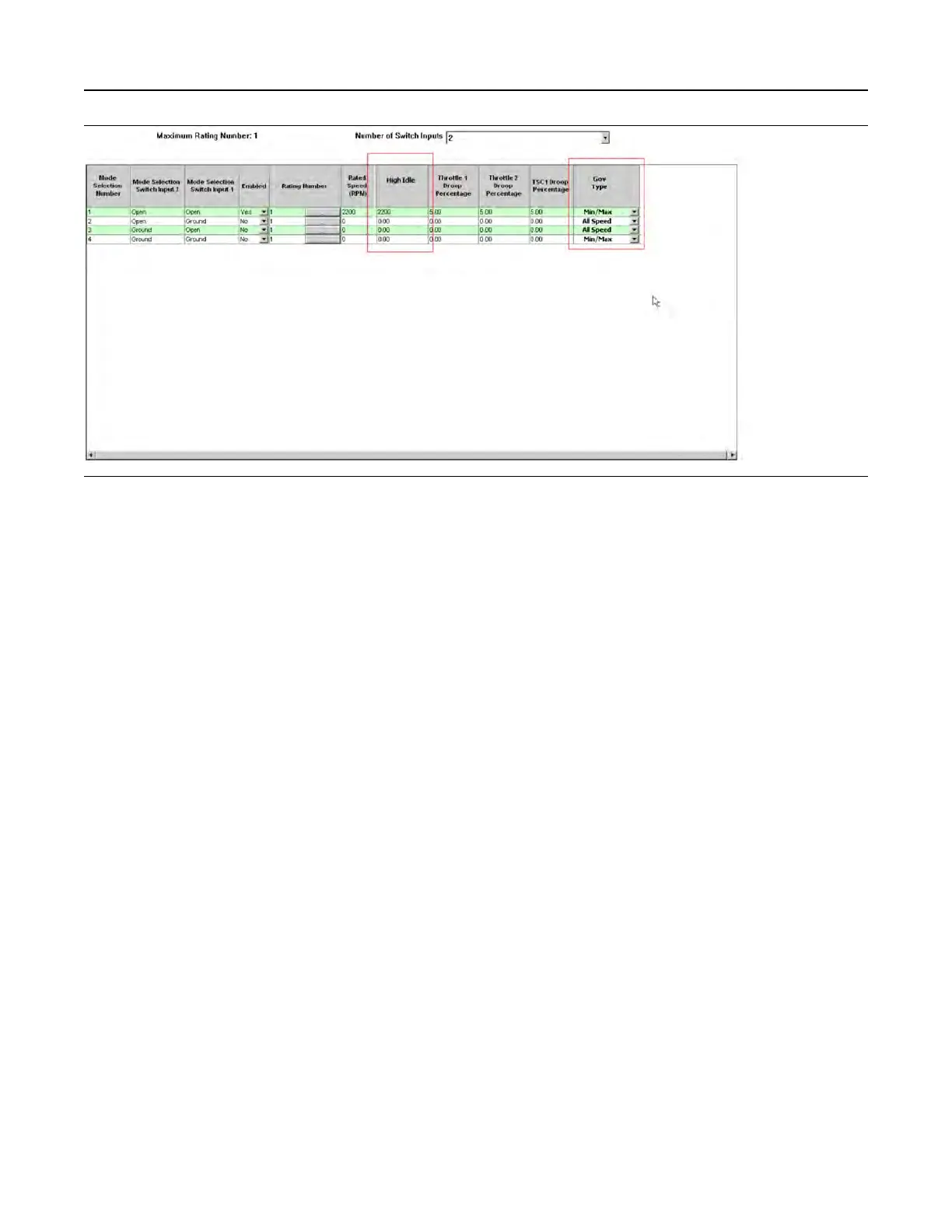
Illustration 181 g03422567
Screen 1
Once the number of required modes and switches
has been selected, each mode must be configured.
Each mode is defined by the following selection:
• Mode Number - (1-4)
• Switch input 1 and 2 combinations to enable the
mode
• Enabled - For example, if only three modes are
required then mode 4 would be set to “NO” . If the
switch combination was active for Mode 4, the
ECM would display a fault code.
• Rating number – This parameter allows any
available ratings in the flash file to be selected.
The specific rating information can be found in the
main configuration screen under “Ratings” .
• Rated Speed – This parameter is configurable
between defined limits in the ECM (for example –
1800 rpm to 2200 rpm).
• High Idle – This parameter is configurable
between 1800 rpm and 2800 rpm but also limited
to 112% of the programmed rated speed.
• Throttle Channel 1 Droop Value – This parameter
is configurable between 0-10%.
• Throttle Channel 2 Droop Value – This parameter
is configurable between 0-10%.
• TSC1 Droop Value – This parameter is
configurable between 0-10%.
• Governor Type – This parameter can be
configured to “All Speed” governing or “Min Max”
governing using the drop-down box.
Once the mode configuration has been set, the
submit button must be clicked at the bottom of the
page. The ECM power must be cycled from off to on.
The status of the mode switch inputs can be
monitored on the status screen in the electronic
service tool.
Maintenance Indicator
This feature is configured through the main
configuration screen in the electronic service tool.
UENR4469-36 483
Service
Copyright of Perkins Engine Company Limited. NOT FOR REPRINTING OR RESALE