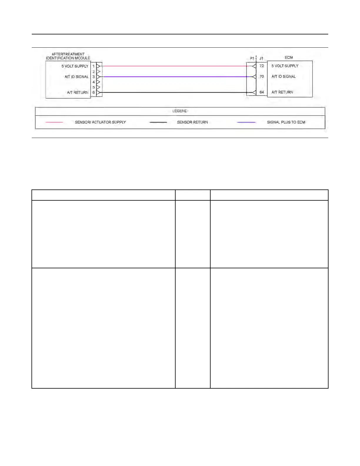
Illustration 92 g03671526
Schematic for the aftertreatment identification module
Not all connectors are shown. Refer to the appropriate Electrical Schematic.
Complete the procedure in the order in which the
steps are listed.
Table 148
Troubleshooting Test Steps
Values Results
1. Check for Diagnostic Codes
A. Establish communication between the electronic service tool and
the Dosing Control Unit (DCU) . Refer to Troubleshooting, “Elec-
tronic Service Tools”, if necessary.
B. Turn the keyswitch to the ON position.
C. Look for “-2” or “ -8” active or logged codes.
Diagnostic
code
Result: A 5576-2 or 3468-2 diagnostic code is active.
Proceed to Test Step 6.
Result: A 5576-8 or 3468-8 diagnostic code is active.
Proceed to Test Step 2.
2. Inspect Electrical Connectors and Wiring
A. Inspect the P1/J1 connector. Refer to Troubleshooting, “Electrical
Connectors - Inspect” for details.
B. Inspect the connector for the aftertreatment identification module.
Refer to Troubleshooting, “Electrical Connectors - Inspect” for
details.
C. Perform a 45 N (10 lb) pull test on each of the wires in the ECM
connector that are associated with the aftertreatment identification
module.
D. Check the screw for the ECM connector for the correct torque of
6 N·m (53 lb in).
E. Check the harness for abrasion and pinch points from the after-
treatment identification module back to the ECM.
Connectors
and wiring
Result: There is a fault with the harness and
connectors.
Repair: Repair the connectors or the harness and/or re-
place the connectors or the harness. Ensure that all of
the seals are correctly in place and ensure that the con-
nectors are correctly connected.
Use the electronic service tool in order to clear all
logged diagnostic codes and then verify that the repair
has eliminated the fault.
Result: All connectors, pins, and sockets are correctly
coupled and/or inserted. The harness is free of corro-
sion, abrasion, and pinch points.
Proceed to Test Step 3.
(continued)
UENR4469-36 269
Circuit Tests
Copyright of Perkins Engine Company Limited. NOT FOR REPRINTING OR RESALE