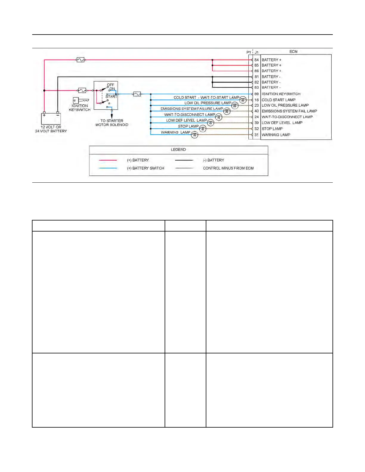
Illustration 115 g03712946
Typical schematic of the circuit for the indicator lamps
Not all connectors are shown. Refer to the appropriate Electrical Schematic.
Table 187
Troubleshooting Test Steps
Values Results
1. Inspect Electrical Connectors and Wiring
A. Turn the keyswitch to the OFF position.
B. Check that the fuses are not blown.
C. Thoroughly inspect the P1 connector and the lamp connec-
tions. Refer to Troubleshooting, “Electrical Connectors - In-
spect” for details.
D. Perform a 45 N (10 lb) pull test on each of the wires in the
P1 connector that are associated with the indicator lamps.
E. Check the screw for the ECM connector for the correct tor-
que of 6 N·m (53 lb in).
F. Check the harness for abrasions and for pinch points from
the battery to the ECM.
Loose connection
or damaged wire
Result: There is a fault in a connector or the wiring.
Repair: Repair any faulty connectors or replace the wiring
harness. Ensure that all of the seals are properly in place
and ensure that the connectors are correctly coupled.
Replace any blown fuses.
Use the electronic service tool to verify that the repair elimi-
nates the fault.
Result: All connectors, pins, and sockets are correctly
coupled and/or inserted. The harness is free of corrosion,
abrasion, and pinch points. The fuses are not blown.
Proceed to Test Step 2.
2. Inspect the Lamp
A. Disconnect the lamp from the harness. Inspect the lamp in
order to determine if the lamp has failed.
B. Measure the resistance across the two terminals of the
lamp.
Less than 2000
Ohms
Result: The lamp has greater than 2000 Ohms resistance.
Repair: Replace the suspect lamp.
Use the electronic service tool to verify that the repair elimi-
nates the fault.
Result: The lamp has less than 2000 Ohms resistance.
Proceed to Test Step 3.
(continued)
342 UENR4469-36
Circuit Tests
Copyright of Perkins Engine Company Limited. NOT FOR REPRINTING OR RESALE