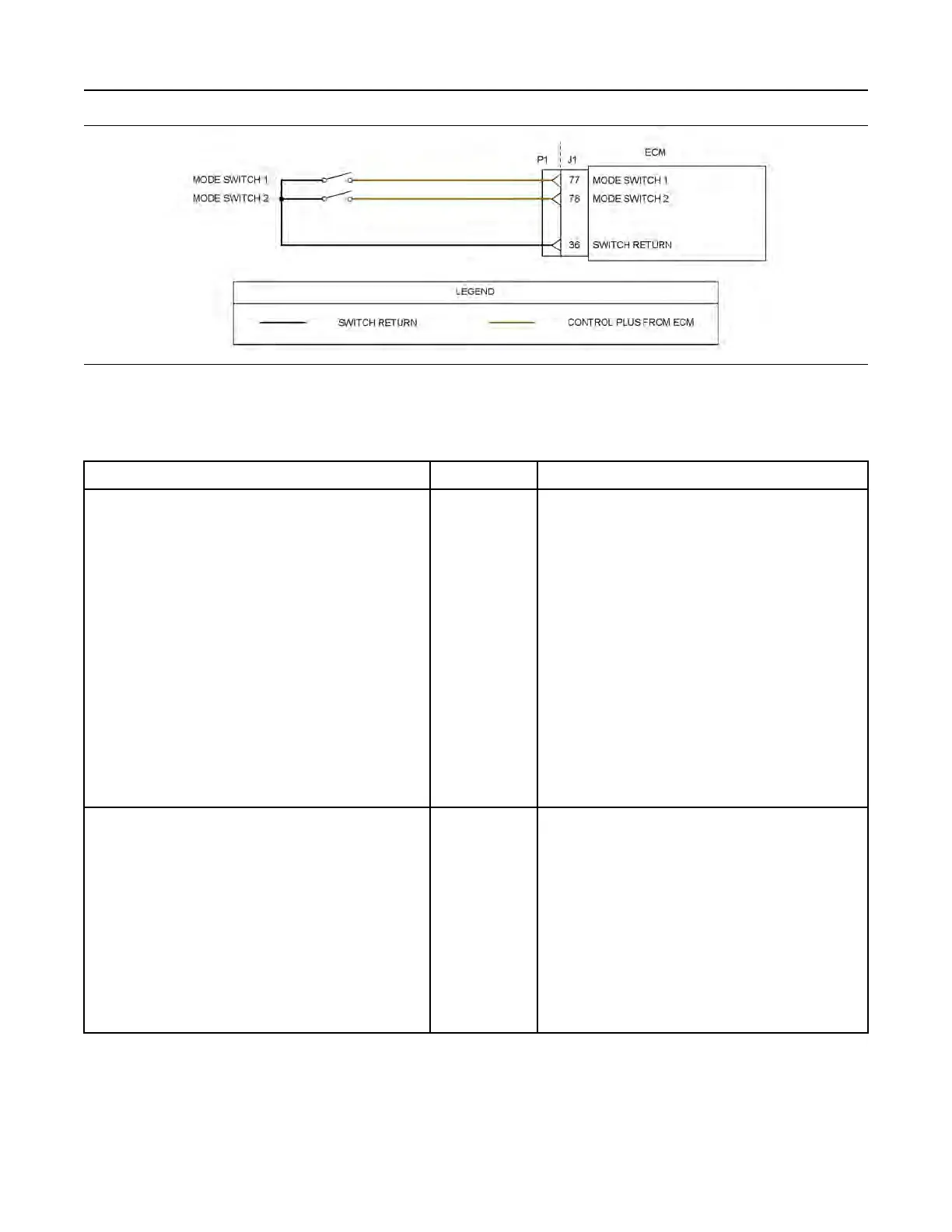
Illustration 122 g03713315
Schematic for the mode selection switch
Not all connectors are shown. Refer to the appropriate Electrical Schematic
Table 194
Troubleshooting Test Steps
Values Results
1. Inspect Electrical Connectors and Wiring
A. Turn the keyswitch OFF.
B. Thoroughly inspect the P1 connector. Thoroughly inspect
the mode switch connectors, plugs, and interconnections on
the harness. Refer to Troubleshooting, “Electrical Connectors
- Inspect” for details.
C. Perform a 45 N (10 lb) pull test on each of the wires in the
P1 connector that are associated with the mode selector
switches.
D. Check the screw for the ECM connector for the correct tor-
que of 6 N·m (53 lb in).
E. Check the harness for abrasions and for pinch points from
the mode section switches to the ECM.
Loose connection
or damaged wire
Result: There is a fault in a connector or the wiring.
Repair: Repair any faulty connectors or replace the wiring
harness. Ensure that all of the seals are properly in place
and ensure that the connectors are correctly coupled.
Use the electronic service tool to clear all logged diagnostic
codes and verify that the repair eliminates the fault.
Result: All connectors, pins, and sockets are correctly
coupled and/or inserted. The harness is free of corrosion,
abrasion, and pinch points.
Proceed to Test Step 2.
2. Check the Status of the Mode Selection Switch
A. Turn the keyswitch to the OFF position.
B. Connect the electronic service tool to the diagnostic
connector.
C. Turn the keyswitch to the ON position.
D. Monitor the status screen on the electronic service tool.
Cycle the mode switch to the ON position and to the OFF
position.
Switch status
changes
Result: The switch status changes on the electronic serv-
ice tool as the mode switches are cycled.
Use the electronic service tool to clear all logged diagnostic
codes. Return the engine to service.
Result: The switch status does not change as the mode
switches are cycled.
Proceed to Test Step 3.
(continued)
UENR4469-36 353
Circuit Tests
Copyright of Perkins Engine Company Limited. NOT FOR REPRINTING OR RESALE