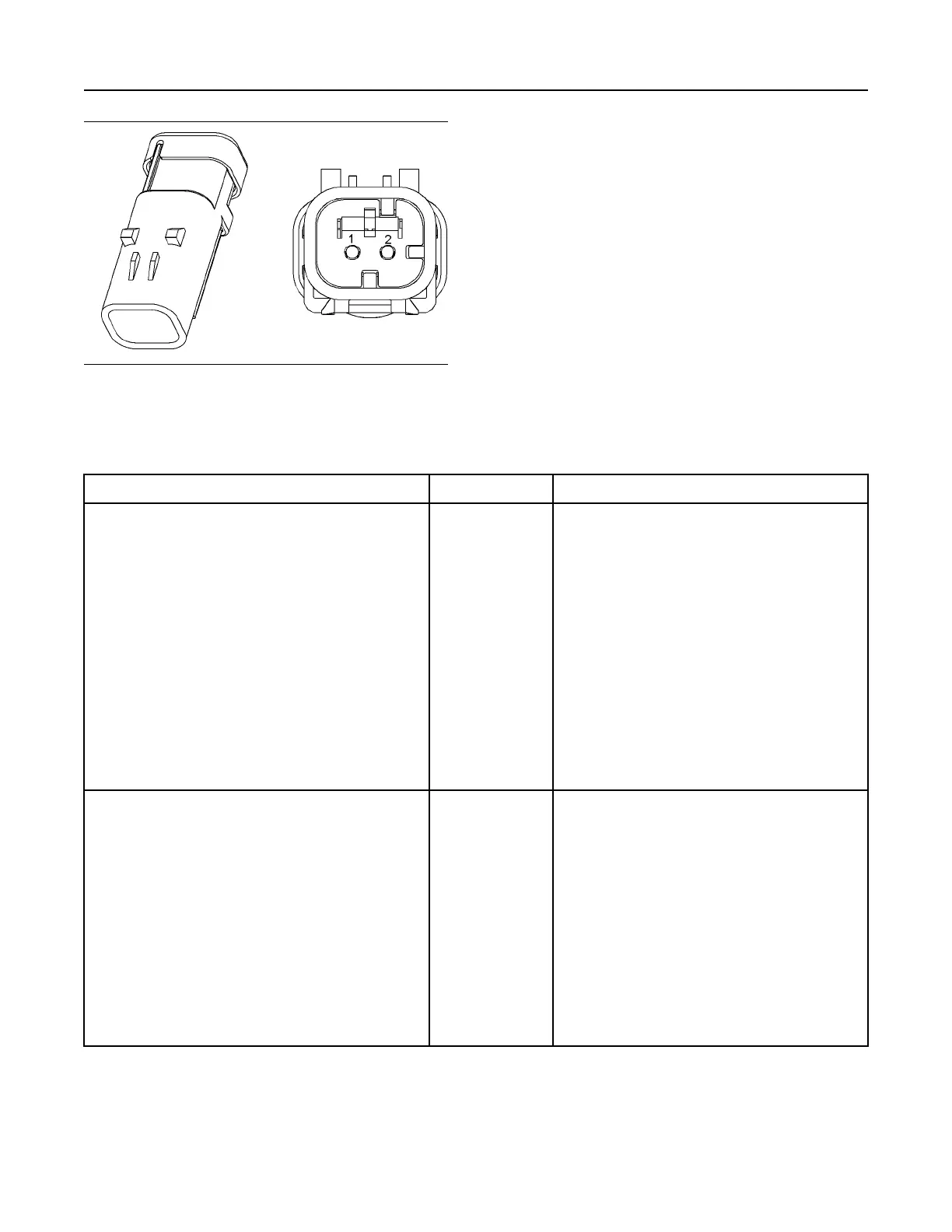
Illustration 150 g01971875
Connector for the wastegate regulator
(1) Signal
(2) Return
Table 220
Troubleshooting Test Steps
Values Results
1. Inspect Electrical Connectors and Wiring
A. Thoroughly inspect the terminal connections on the P2/J2
ECM connector and the solenoids. Refer to Troubleshooting,
“Electrical Connectors - Inspect”.
B. Perform a 45 N (10 lb) pull test on each of the wires in the
ECM connector and the solenoid connectors that are associ-
ated with the active diagnostic code.
C. Check the screw for the ECM connector for the correct tor-
que of 6 N·m (53 lb in).
D. Check the harness for corrosion, abrasion, and pinch points
from the solenoids to the ECM.
Loose connection or
damaged wire
Result: There is a fault in a connector or the wiring.
Repair: Repair any faulty connectors or replace the wir-
ing harness. Ensure that all of the seals are properly in
place and ensure that the connectors are correctly
coupled.
Use the electronic service tool to clear all logged diag-
nostic codes and verify that the repair eliminates the
fault.
Result: All connectors, pins, and sockets are correctly
coupled and/or inserted. The harness is free of corro-
sion, abrasion, and pinch points.
Proceed to Test Step 2.
2. Check for Active Diagnostic Codes
A. Turn the keyswitch to the OFF position.
B. Connect the electronic service tool to the diagnostic
connector.
C. Turn the keyswitch to the ON position. Wait at least 20 sec-
onds for activation of the diagnostic codes.
D. Verify if any of the diagnostic codes that are listed in Table
219 are active.
E. Turn the keyswitch to the OFF position.
Diagnostic codes Result: A -5 diagnostic code is active.
Proceed to Test Step 3.
Result: A -6 diagnostic is active.
Proceed to Test Step 5.
(continued)
412 UENR4469-36
Circuit Tests
Copyright of Perkins Engine Company Limited. NOT FOR REPRINTING OR RESALE