Adjustment
14 - 2
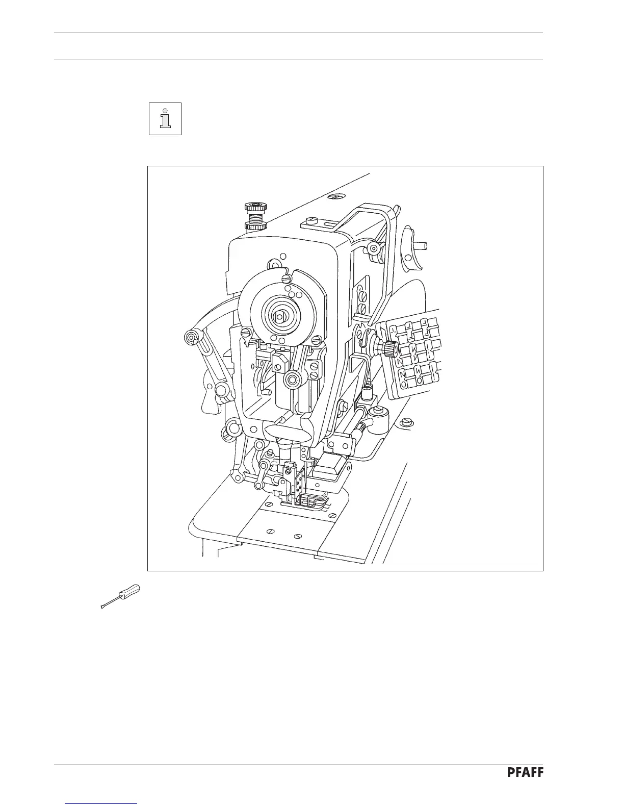
14.03 Check and adjustment aid
By placing pegs in holes 1 and 3 - 6 the required needle bar positions can be
exactly fixed.
● Turn the handwheel until the needle bar has approximately reached the required position.
● Place the 5 mm rig pin in the appropriate hole and put pressure on it.
● Turn the handwheel forwards and backwards a little until the rig pin moves into the slot
in the crank behind the bearing plate, thus blocking the machine.
Hole 1 = 0.6 mm after the top dead center of the needle bar (0.6 a. TDC)
Hole 3 = 0.6 mm after the bottom dead center of the needle bar (0.6 a. BDC)
Hole 4 = 1.8 mm after the bottom dead center of the needle bar (needle rise)
Hole 5 = Top dead center of the needle bar (TDC)
Hole 6 = 4 mm after the bottom dead center of the needle bar (4 a. BDC)
Fig. 14 - 01
5
1
4
6
3