Published by EL 0666 BG CD Customer Service Printed in the Netherlands Subject to modification EN 3122 785 15910
©
Copyright 2006 Philips Consumer Electronics B.V. Eindhoven, The Netherlands.
All rights reserved. No part of this publication may be reproduced, stored in a
retrieval system or transmitted, in any form or by any means, electronic,
mechanical, photocopying, or otherwise without the prior permission of Philips.
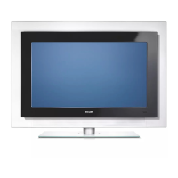
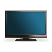
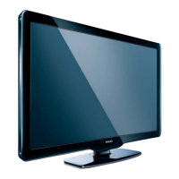
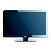
Color Television Chassis
BJ2.4U/BJ2.5U
LA
ENTRY
EDGE
G_15930_000.eps
200606
TOP A
TOP B
Contents Page Contents Page
1. Technical Specifications, Connections, and Chassis
Overview 2
2. Safety Instructions, Warnings, and Notes 5
3. Directions for Use 7
4. Mechanical Instructions 8
5. Service Modes, Error Codes, and Fault Finding 15
6. Block Diagrams, Test Point Overviews, and
Waveforms
Wiring Diagram 37” Entry 39
Wiring Diagram 42” Top A 40
Wiring Diagram 42” Top B 41
Block Diagram Display Supply 37” Entry 42
Block Diagram Display Supply 42” Top 43
Display Supply (Sanken) 44
Block Diagram Platform Supply 42” Top 45
Block Diagram Video 46
Block Diagram Audio 47
Block Diagram Control 48
I2C IC’s Overview 49
Supply Lines Overview 37” Entry 50
Supply Lines Overview 42” Top 51
7. Circuit Diagrams and PWB Layouts Drawing PWB
LCD Supply (37”): Mains Filter + Standby (A1) 52 54-59
LCD Supply (37”): Supply (A2) 53 54-59
Ambi Light (Part 1) (AL1) 60 63
Ambi Light (Part 2) (AL2) 61 63
Ambi Light (Part 3) (AL3) 62 63
Platform Supply 42”: Aux Supply (AP1) 64 72-78
Platform Supply 42”: Stby Supply (AP2) 65 72-78
Platform Supply 42”: Filter (AP3) 66 72-78
Platform Supply 42”: Audio Left/Right (AP4) 67 72-78
Platform Supply 42”: Audio Prot / Mute (AP5) 68 72-78
Platform Supply 42”: Audio Sub Woofer (AP6) 69 72-78
Platform Supply 42”: Audio Centre (AP7) 70 72-78
Platform Supply 42”: SRP List 71
Small Signal Board (B1-B12) 79-117 120-125
SRP List Explanation 117
SSB: SRP List Part 1 118
SSB: SRP List Part 2 119
External I/O Panel: Externals A (BE1) 126 128
External I/O Panel: Externals B (BE2) 127 128
Side I/O Panel (Top) (D) 129 130
Side I/O Panel (Entry) (D) 131 132
Control Board (Top) (E) 133 133
Control Board (Entry) (E) 134 134
LED Panel (Top) (J) 135 136
LED Panel (Entry) (J) 137 138
Standby & Audio Panel: Connections (SA1) 139 142-144
Standby & Audio Panel: Standby (SA2) 140 142-144
Standby & Audio Panel: Audio (SA3) 141 142-144
8. Alignments 145
9. Circuit Descriptions, Abbreviation List, and IC Data
Sheets 150
Abbreviation List 170
IC Data Sheets 173
10. Spare Parts List 186
11. Revision List 201
