UM EN AXL E SYS INST
24 / 58
PHOENIX CONTACT 8395_en_03
3.6 Diagnostics and status indicators
of the Axioline E devices
Diagnostics The diagnostics indicators (green/yellow/red) indicate whether an error is present or not.
In the event of an error, they indicate the error type and location.
Status The status indicators (yellow) indicate the signal state of the corresponding input/output or
of the IO-Link port. If the yellow status indicators are on, this indicates signal state “1” of the
input/output signal.
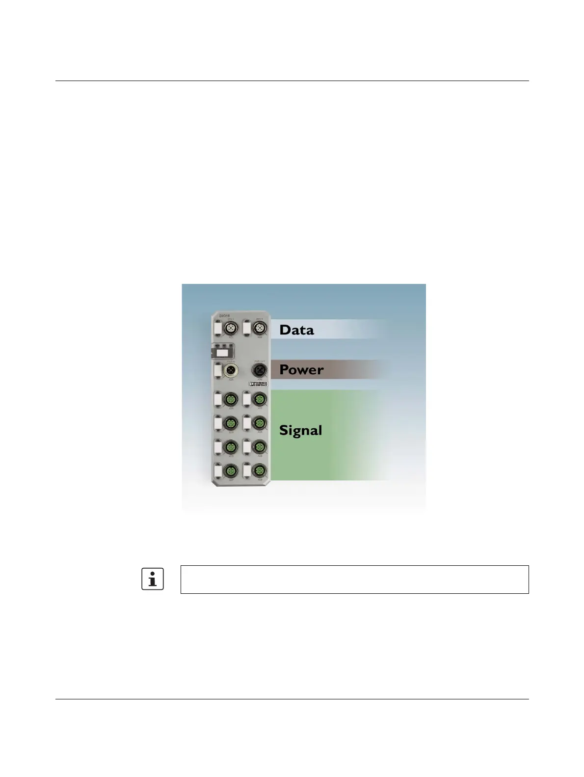
The Axioline E devices have three main areas for diagnostics and status indicators.
– Indicators for the network/bus system (network/bus-specific) - data
– Indicators for the power supplies - power
– Indicators for the inputs and outputs and the IO-Link ports (device-specific) - signal
These areas are shown in Figure 3-9.
Figure 3-9 Main diagnostics and status indicators of the Axioline E devices
For more detailed information on the diagnostics and status indicators, please refer to the
data sheet for the respective device.
 Loading...