Mounting Axioline E devices and connecting cables
8395_en_03 PHOENIX CONTACT 37
4.8 Connecting power supplies
For Axioline E devices, a distinction is made between two voltages:
–U
S
to supply the communications power and the sensors (always required)
–U
A
for supplying the actuators, only required for devices with fixed outputs or for addi-
tional devices
Connection All supply voltages are connected via M12 connectors.
Current carrying capacity
4.8.1 Power supplies U
S
and U
A
Voltages U
S
and
U
A
are fed in at connection X31.
Power supply U
S
is required to supply the communications power of the device electronics
and to supply the sensors. It must be connected to every device. If this supply voltage is
disconnected, the device will not work.
Install the power supply for the device electronics independently of the power supply for the
actuators. Protect the power supplies independently. This means that the bus can continue
running even if some I/O devices are switched off.
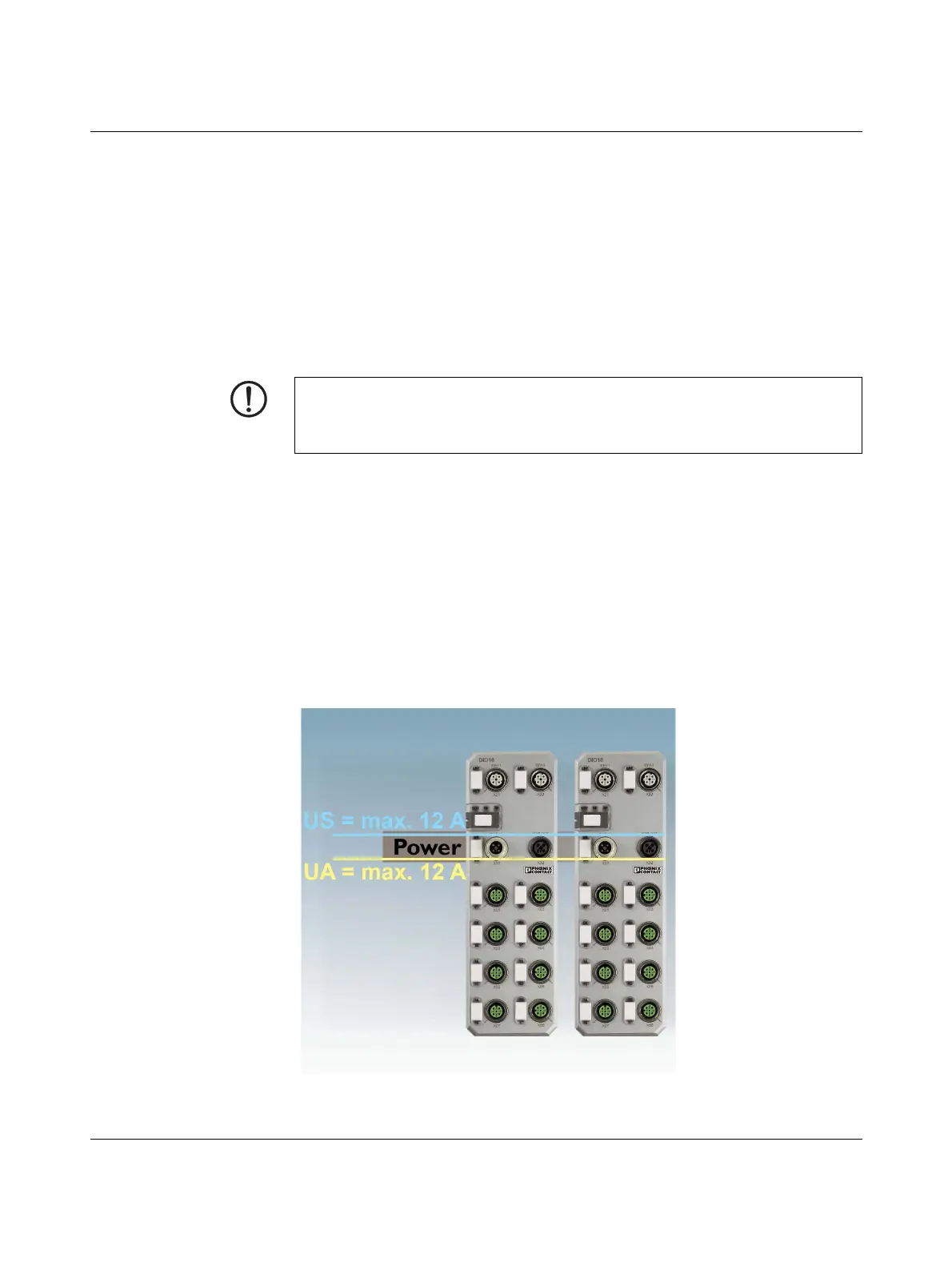
Figure 4-15 Voltage feed U
S
and U
A
NOTE: Damage to the electronics
Connect both supply voltages completely (to +24 V and GND). Do not connect several
supply voltages via one GND, as this will exceed the current carrying capacity of the con-
tacts.
 Loading...