UM EN AXL E SYS INST
40
PHOENIX CONTACT 8395_en_03
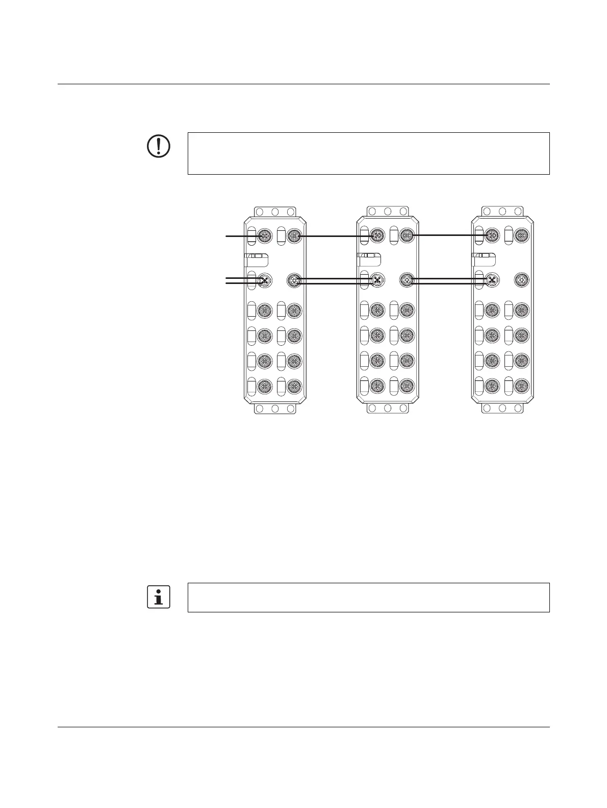
4.8.3 Examples for voltage supply
Figure 4-19 Example for the supply and forwarding of supply voltages
4.8.4 Supply line and power supply (M12)
For M12 connectors in Axioline E devices, a maximum of 12 A per contact is permitted.
To ensure that this condition is met, the following factors must be considered:
1. Current consumption of the Axioline E devices (see data sheets)
2. Current consumption of the connected sensors
3. Current consumption of the connected actuators
4. Length of the cables and losses on these cables
NOTE: Damage to the electronics
The total current at U
S
must not exceed 12 A.
The total current at U
A
must not exceed 12 A.
It is particularly important that these factors are observed when forwarding the supply
voltage.
BUS IN BUS OUT
X21 X22
PWR IN PWR OUT
X31 X32
X01 X02
X03 X04
X05 X06
X07 X08
BUS IN BUS OUT
X21 X22
PWR IN PWR OUT
X31 X32
X01 X02
X03 X04
X05 X06
X07 X08
DI16
DI8 DO4 2A DI8 DO8
BUS IN BUS OUT
X21 X22
PWR IN PWR OUT
X31 X32
X01 X02
X03 X04
X05 X06
X07 X08
BUS
S
U
U
A
 Loading...