Axioline E IO-Link devices
8395_en_03 PHOENIX CONTACT 47
5.2.2 Basic structure of the Axioline E IO-Link
digital input and output devices
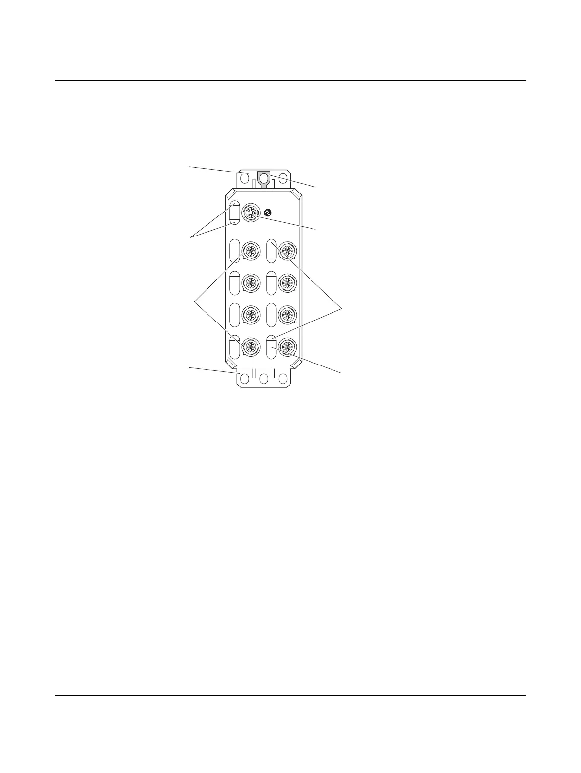
The figure shows the basic structure of the Axioline E IO-Link digital input and output
devices.
Figure 5-4 Basic structure of the Axioline E IO-Link digital input and output devices
1 Fixing clips
2 FE connection)
3 Status indicators of the IO-Link port
4 IO-Link A port (digital input device)
IO-Link B port (digital output device)
5 Connections of the IO-Link ports (inputs or outputs)
6 Status indicators of the IO-Link port (inputs or outputs)
7 Markers for marking
X21
X21
X01 X02
X04X03
X05 X06
X08X07
6
1
1
7
3
5
4
2
 Loading...