Mounting Axioline E devices and connecting cables
8395_en_03 PHOENIX CONTACT 41
4.8.5 Calculation example for sensor and actuator currents
The calculation example applies to the assignment of one signal per port.
Calculation example for an
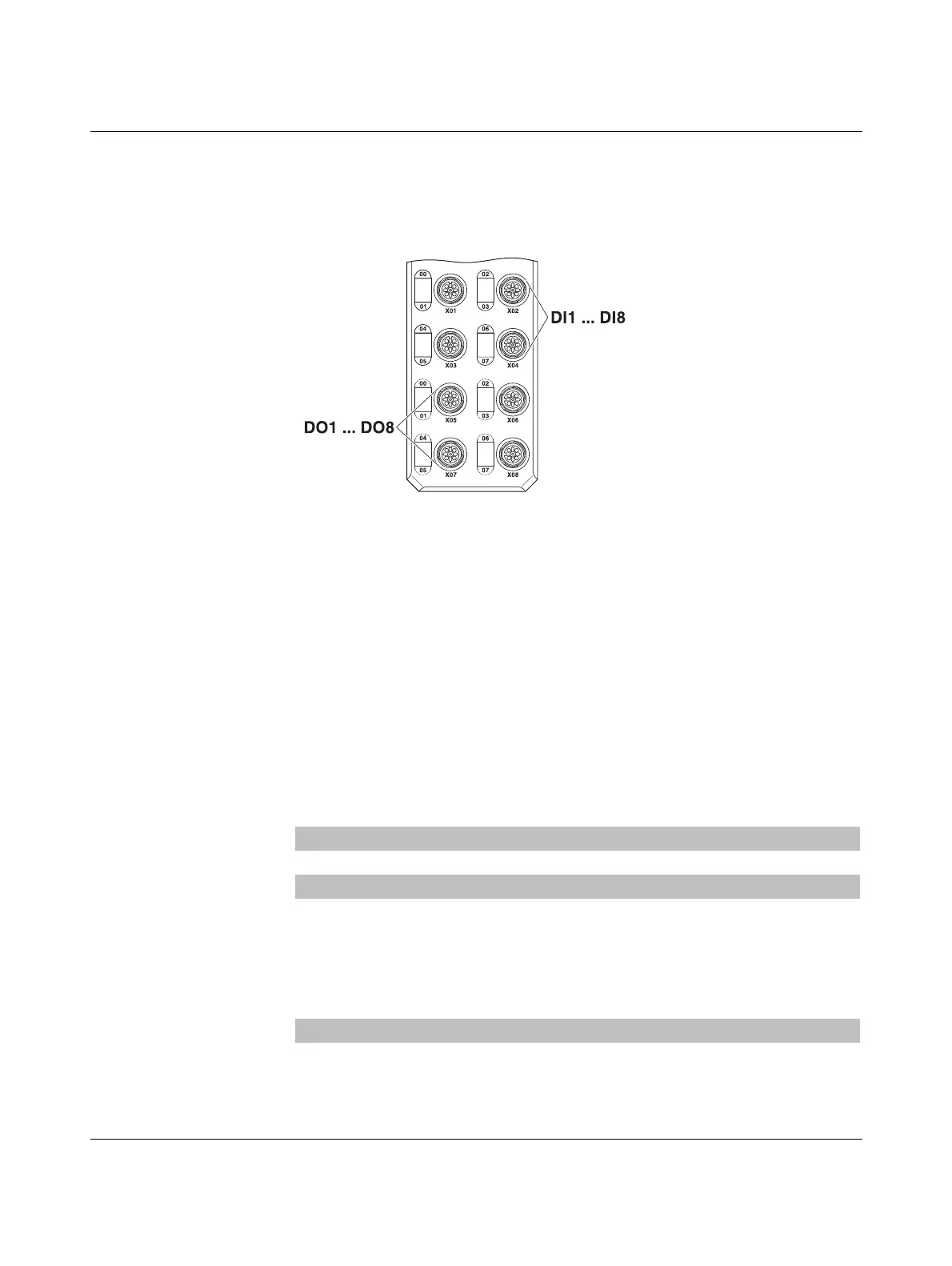
AXL E DI8 DO8 device
Figure 4-20 AXL E PB DI8 DO8 M12 6P
Type of sensor: Current consumption:
1 x reflex photoelectric barrier with 2 output signals 30 mA
2 x proximity switch 15 mA each
Type of actuator:
2 x solenoid valve (hydraulic) 1.3 A each
2 x solenoid valve (pneumatic) 67 mA each
Calculation example for an AXL E DI8 DO8 device
U
S
Installation consumption 165 mA
X01, X02 Reflex photoelectric barrier + 30 mA
X03 Proximity switch + 15 mA
X04 Proximity switch + 15 mA
Sensor supply = 225 mA
Current consumption of inputs (5 mA for each input used) + 20 mA
I
U
total = 245 mA
Current consumption of actuators U
A
U
A
Installation consumption 30 mA
X05 2 x 1.3 A solenoid valve (hydraulic) + 2.6 A
X06 2 x 67 mA solenoid valve (pneumatic) + 134 mA
I
UA
total = 2.764 A
With this wiring, the device loads U
S
with approximately 245 mA and U
A
with
approximately 2.764 A.
 Loading...