Axioline E IO-Link devices
8395_en_03 PHOENIX CONTACT 49
5.2.5 Mounting of the Axioline E IO-Link
digital input and output devices
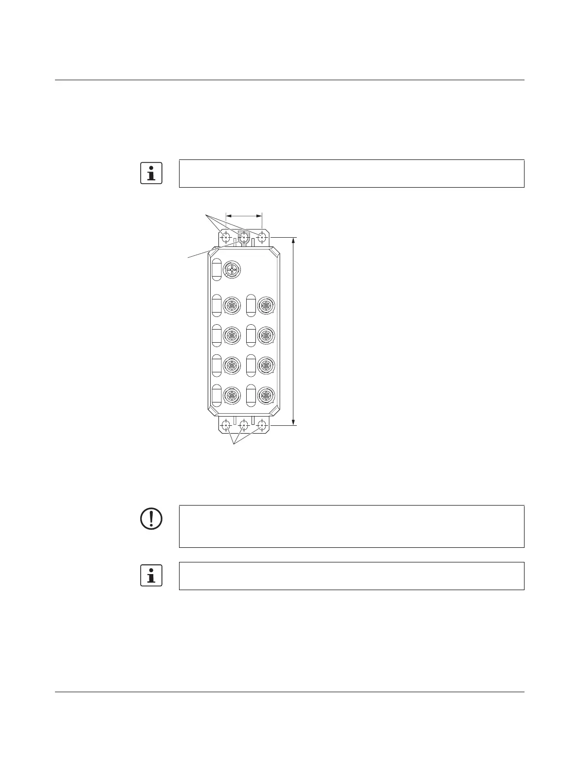
Screw the devices tightly down onto a flat surface using the fixing clips (1 in Figure 5-5).
Ground the devices by means of the grounding lug (2 in Figure 5-5).
Drill hole spacing
Figure 5-5 Mounting of the Axioline E IO-Link digital input and output devices
Functional earth
grounding
Connecting cables Then connect the cables , see page 36.
Use standard M5 screws with toothed lock washer. Observe the maximum torque of the
screws.
NOTE: Data corruption or loss
Functional earth grounding is crucial for interference-free operation.
Ground the devices by means of the grounding lug.
For more information on the installation, please refer to the packing slip and the chapters
4.1, 4.2 und 4.3.
 Loading...