Axioline E IO-Link devices
8395_en_03 PHOENIX CONTACT 45
5.1 Axioline E IO-Link master
Der Axioline E IO-Link master enables the operation of up to eight IO-Link sensors/actuators
and is also used to acquire digital signals. By using the various operating modes of an
IO-Link port, the following operating modes can be operated:
– Digital standard signal.
– Analogue signals in combination with IO-Link/analog converters
– IO-Link device communication, flow sensors, valve inserts, light barriers or distance
meters
With the multifunctional IO-Link ports, an IO-Link master becomes a universal I/O device. In
conjunction with the IO-Link /analog converters, a perfect solution scenario results for the
multifaceted advent of analog signals. Together with the IO-Link/analog converters, the de-
vices allow flexible processing of the signal volume in the field installation.
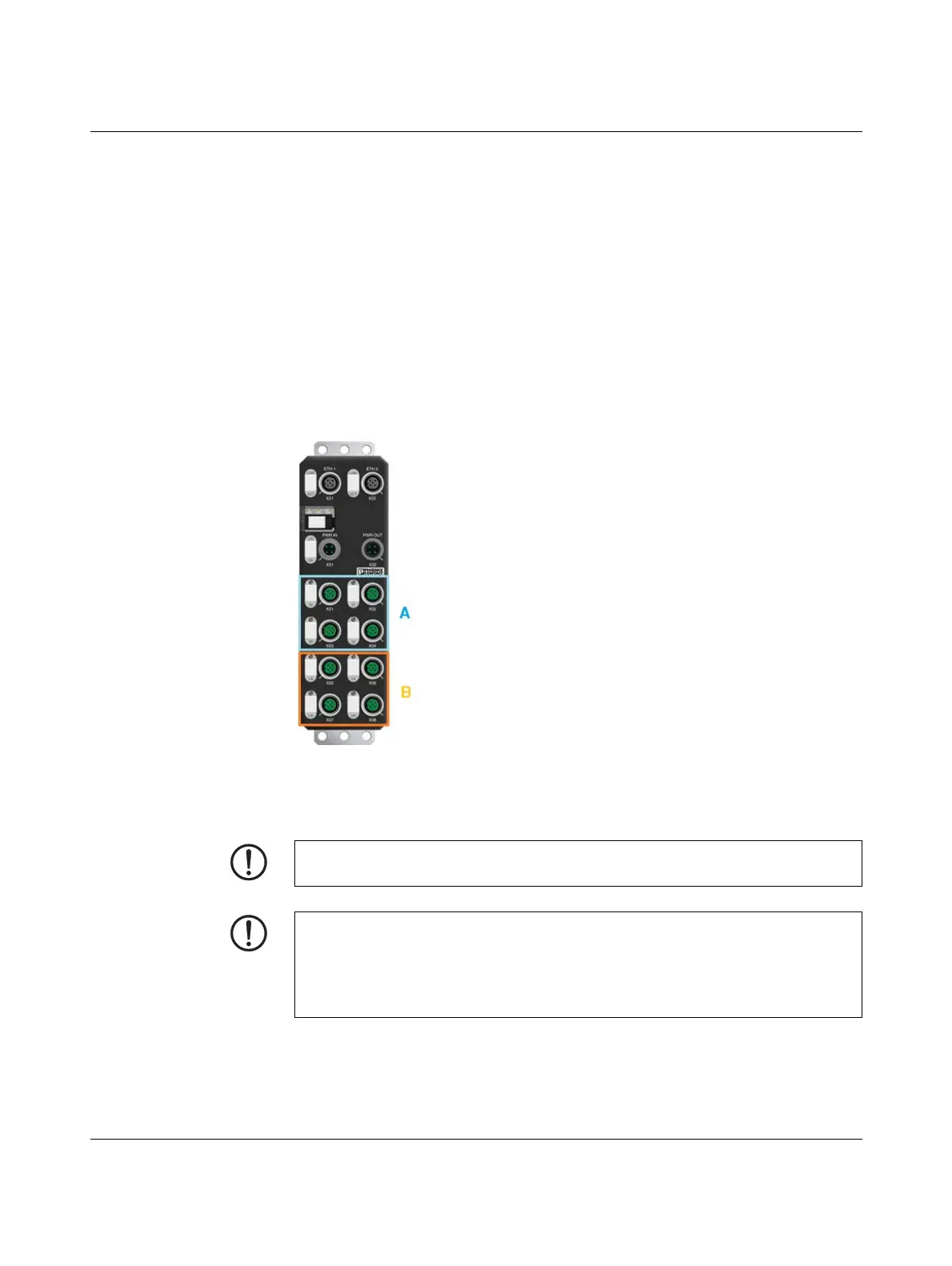
Figure 5-2 IO-Link A ports (A) und IO-Link B ports (B) of an AXL E IO-Link masters
Ensure that the voltage supply U
A
and the power supply U
S
are made from two indepen-
dent, galvanically isolated power supplies.
NOTE: Sensors damage
When connecting an IO-Link type A sensor to an IO-Link B port, note that a voltage is
applied to pin 2 and pin 5. Do not connect it to the sensor.
Use a three-wire cable between port and sensor,
cable type SAC-3P-MS SCO / ... / ... Order No. 1523515.
 Loading...