UM EN AXL E SYS INST
38
PHOENIX CONTACT 8395_en_03
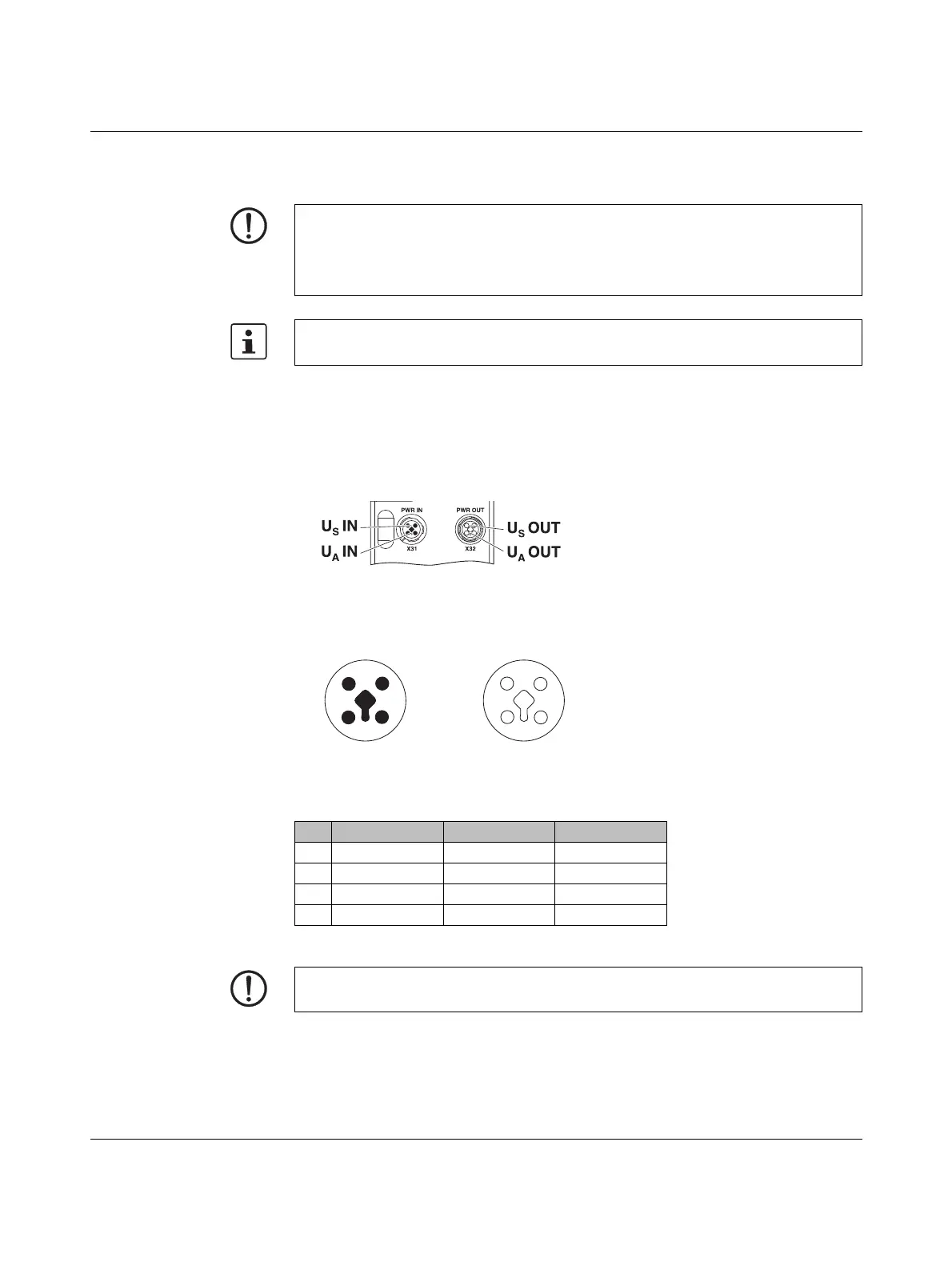
Power supply U
S
for AXL E devices
Connect power supply U
S
for the logic and sensors to socket X31. To supply additional de-
vices, connect the cable for the outgoing supply voltage to socket X32.
Power supply U
A
for AXL E devices
Power supply U
A
is required to supply the actuators. It is only connected to devices with
outputs or is required for additional devices.
When determining the load for a supply voltage, take into account the number of outputs,
the nominal current, and the simultaneity.
Figure 4-16 Connections U
S
and U
A
Pin assignment of
power supplies U
S
and U
A
Figure 4-17 Power supplies U
S
and U
A
NOTE: Damage to the electronics
The current carrying capacity of the M12 connectors is 12 A per contact. Make
sure that this value is not exceeded. Please note that the connection for the outgoing sup-
ply voltage is not monitored for overload. If the permissible current carrying capacity is ex-
ceeded, this may result in damage to the connectors.
Phoenix Contact recommends using pre-assembled cables.
Pin IN OUT Wire colors
1+24VDC (U
S
)+24VDC (U
S
)Brown
2GND (U
A
)GND (U
A
)White
3GND (U
S
)GND (U
S
)Blue
4+24VDC (U
A
)+24VDC (U
A
)Black
NOTE: Damage to the electronics
Power supplies U
S
and
U
A
should only be supplied with SELV.
 Loading...