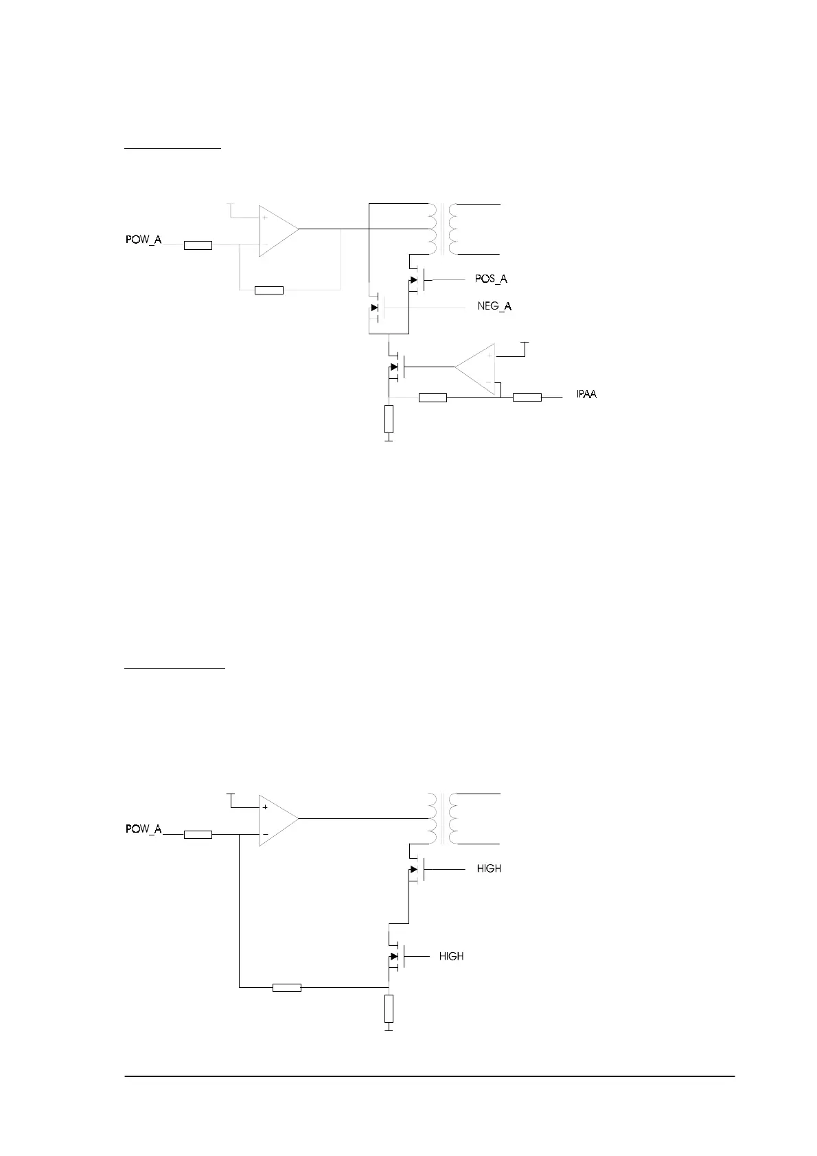
Configuration 1
The circuit can be redrawn as in the figure below.
The output of U9 (TDA 2040) is a DC signal and is connected to the middle connection of the
transformer.
One side of the transformer is connected to Q1 and the other side is connected to Q2. The gates of Q1
and Q2 are connected to POS_A and NEG_A respectively. The soures of Q1 and Q2 are coupled via
Q7 and R3 to ground.
The current through Q7 is controlled by the output of U65. IPAA is a measure for the current through
Q7 and so controls the output amplitude. The measured current (over R3) is fed back to the input of
U65, this way the current is kept constant.
In case of a rectangular or triangular signal the signal at the secondary of the transformer will be
rectified.
Configuration 2:
In comparison with configuration 1 , Q1 will be excluded from the circuit and POS_A and
CURRENT_A will be continuous ‘HIGH’.
The amplitude of POW_A is a measure for the output current and the current is fed back via R3 to
the input of U9, in order to keep the current continuous.
Phyaction Guidance E/C – service manual version 0.5 Page 18