5.4 Ultrasound circuits (only for Guidance C)
5.4.1 PLL
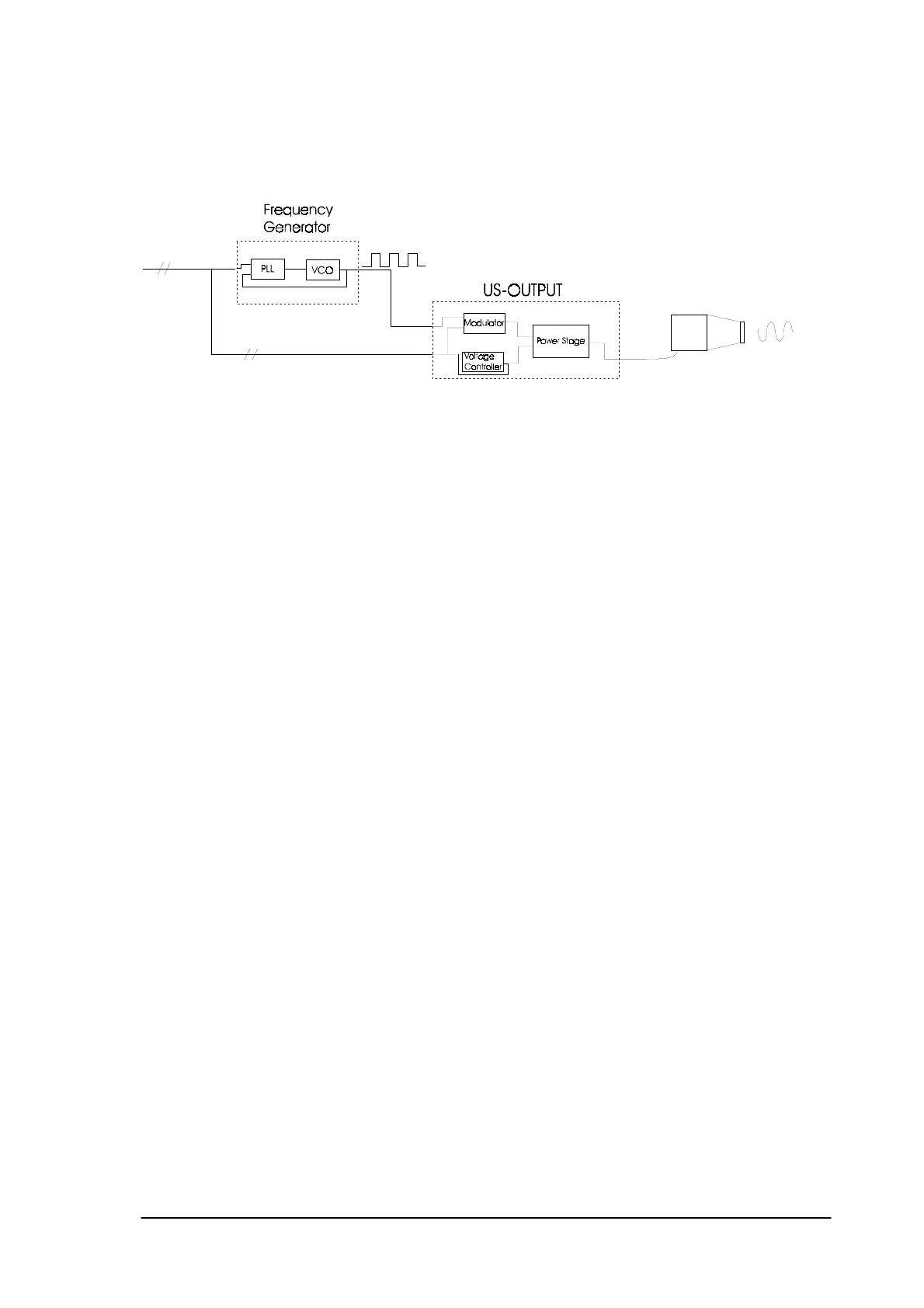
The frequency generator is controlled by the micro controller and it contains a voltage controlled
oscillator and a PLL (phase locked loop).
Each ultrasound crystal has different characteristics. Every crystal is measured during production,
and an optimal working frequency and the ‘bad contact’ frequency is determined.
This means that the ultrasound output stage works on different frequencies according to which head
is connected.
In order to ‘program’ different frequencies, a PLL is used in combination with a VCO.
To obtain a symmetrical steering signal for the power stage the modulator switches its outputs with half
the input frequency. Also the modulator mixes the duty signal synchronously with the ultrasound
frequency to prevent spikes. An amplitude modulation with 100% modulation depth (the signal being
switched on and off) is the result of this mixing.
The calibration values of each ultrasound head are stored in an OTP, which is installed inside the
ultrasound head.
In case of a replacement of the crystal, the OTP has to replaced as well (comes with the crystal)
5.4.2 Voltage controller.
A pulse controlled downward converter voltage controller is used to convert the +24V to the desired
ultrasound voltage. The voltage controller is made in such a way that its output voltage is linear
proportional to its input voltage VUS_set. Thus the micro controller can adjust the ultrasonic power by
setting VUS_setproportional to the square root of the desired output power.
5.4.3 Power stage
The power stage is a switched balance class-D end stage. Power MOSFETs are used as switching
elements. The MOSFETs are driven by buffers (U506) that also take care of a small delay in driving the
MOSFETs, to prevent them of being active simultaneously. If either one of the MOSFETs has become
defective, both of them should be replaced.
Phyaction Guidance E/C – service manual version 0.5 Page 21