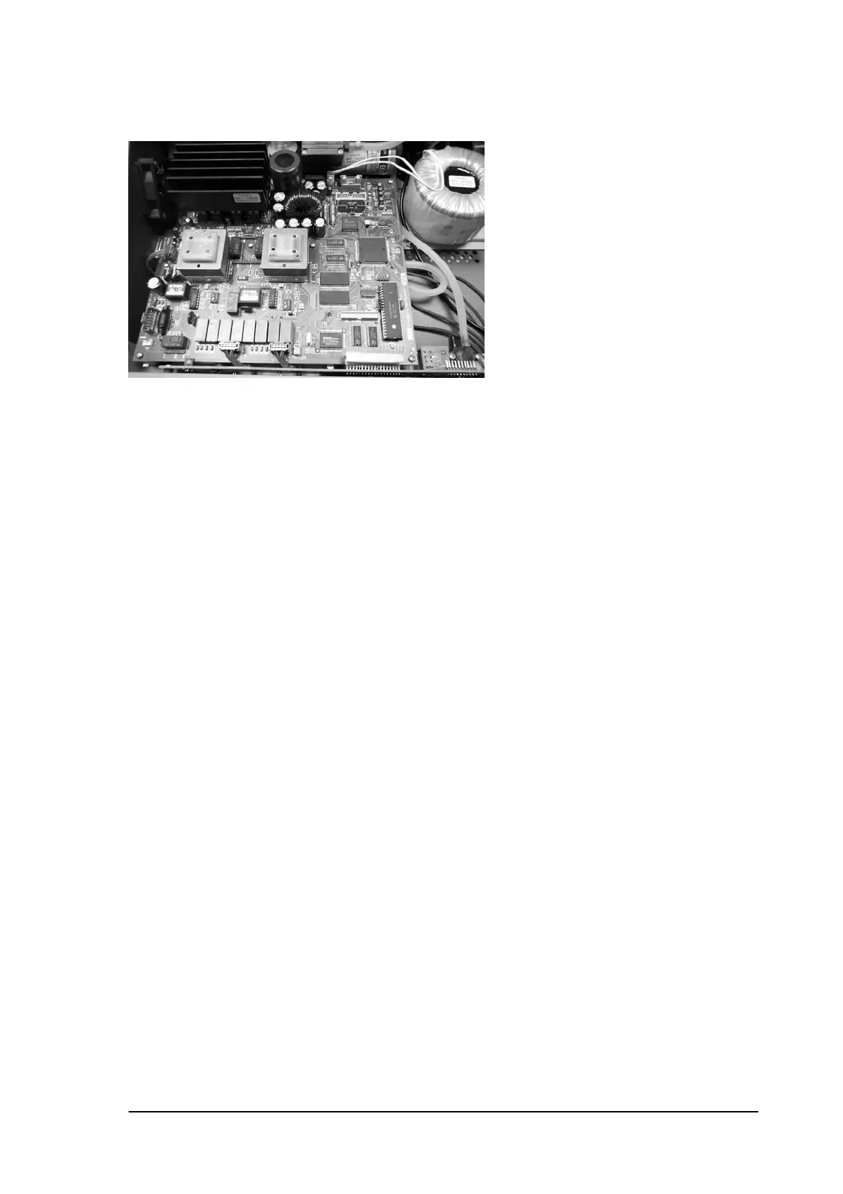
14.2 Main PCB.
Removal: First complete 12.1.
Disconnect the transformer (TRAFO), RS232 connector, ET-channel A connector, ET
channel B connector, Vacuum PCB connector and the FAN connector.
Remove the 6 screws that fix the PCB to the chassis.
Pull the PCB a little bit forwards and take out the PCB.
Caution: To remove the vacuum PCB flatwire, put a smell screwdriver under the flatwire and
pull the complete cable at once out of the connector.
Installation: The installation is in reverse order of the removal procedure.
Cut the vacuum flatwire in several parts in order to put it back, or replace the flatwire.
/ Cut the paper in a way that the internal wires stay perfectly isolated.
14.3 Front cover.
Removal: First complete 12.1 and 12.2
Disconnect the vacuum tubes (pull them off) and the pump connector, the valve
connector and the water level detector.
Remove 2 screws on the left and right side of the cover plus 5 black screws on the
bottom plate and take away the complete front cover.
Caution: Do not pull on the wires to disconnect the cables! Use a small screwdriver to
Lift the connectors out.
Installation: The installation is in reverse order of the removal procedure.
The tube of the vacuum sensor must be installed on the top of the sensor.
Phyaction Guidance E/C – service manual version 0.5 Page 54