Caution:
Installation: The installation is in reverse order of the removal procedure.
Make sure the front LED’s fit exactly into the led holes.
Do not over tighten the screws and the nuts!
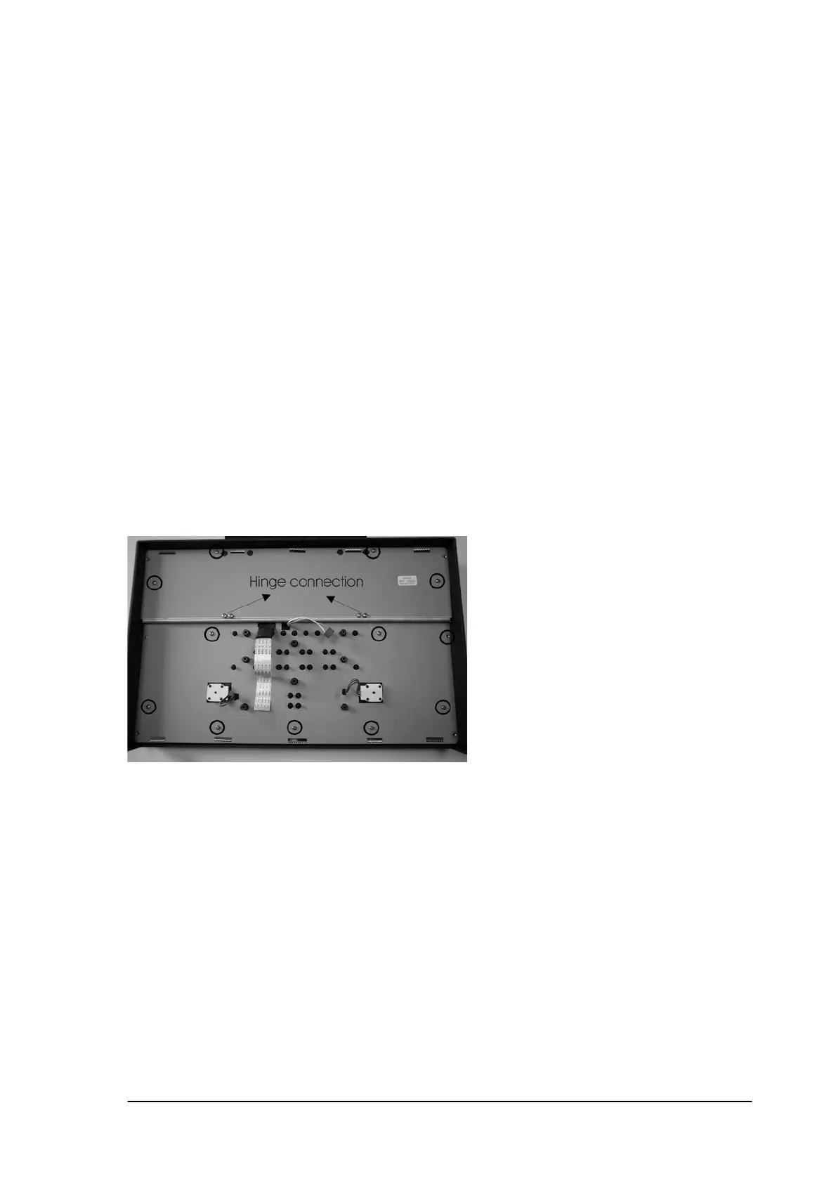
14.6 Keyboard PCB.
Removal: First complete 12.1.
Disconnect the rotary’s of channel A and channel B.
Disconnect the display flatwire.
Disconnect the backlight connector.
Remove the 8 screws that fix the keyboard PCB to the front chassis.
Caution: Open the display connector with a small screwdriver before removing the flatwire.
Installation: The installation is in reverse order of the removal procedure.
Do not over tighten the screws!
14.7 Metal shield.
Removal: First complete 12.1 and 12.6.
Remove the 11 short screws plus 4 long screws of the display hinges .
Lift out the metal shield.
Caution: Do not damage the cables of the rotary’s. If necessary cut off a little bit of the
glue before removing the metal plate.
Installation: The installation is in reverse order of the removal procedure.
Do not over tighten the screws!
Phyaction Guidance E/C – service manual version 0.5 Page 56