14.4 Output filter PCB.
Removal: First complete 12.1, 12.2, 12.3
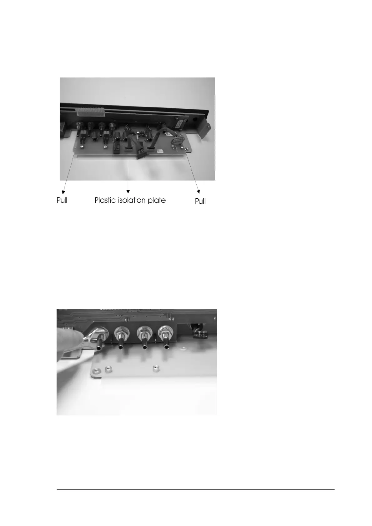
Remove the four screws that fix the output filter PCB onto the front chassis.
GENTLY slide the filter PCB away from the front cover.
Caution: Take the filter PCB on the corner of the PCB and don’t touch the components.
Installation: The installation is in reverse order of the removal procedure.
Do not forget to install the plastic isolation plate under the filter PCB.
14.5 Vacuum PCB.
Removal: First complete 12.1, 12.2, 12.3, 12.4
Remove the 4 M10 nuts that fix the vacuum output connectors.
Remove the 2 screws that fix the vacuum sensor onto the chassis.
Remove the 4 screws that fix the Vacuum PCB to the front chassis.
Phyaction Guidance E/C – service manual version 0.5 Page 55