3. DESCRIPTION OF CONTROLS AND CONNECTORS.
3.1.1 Output connectors and control keys ( drawing unit on last page of service manual).
1.
Tilting display
2. Blue keys for menu option or parameter selection
3.
Blue keys > and < for scrolling through the lists
4.
Key for increasing or setting a parameter
5.
Key for decreasing or setting a parameter
6. Key for channel choice A
7.
Key for channel choice B
8.
Amplitude controller for channel A
9.
Amplitude controller for channel B
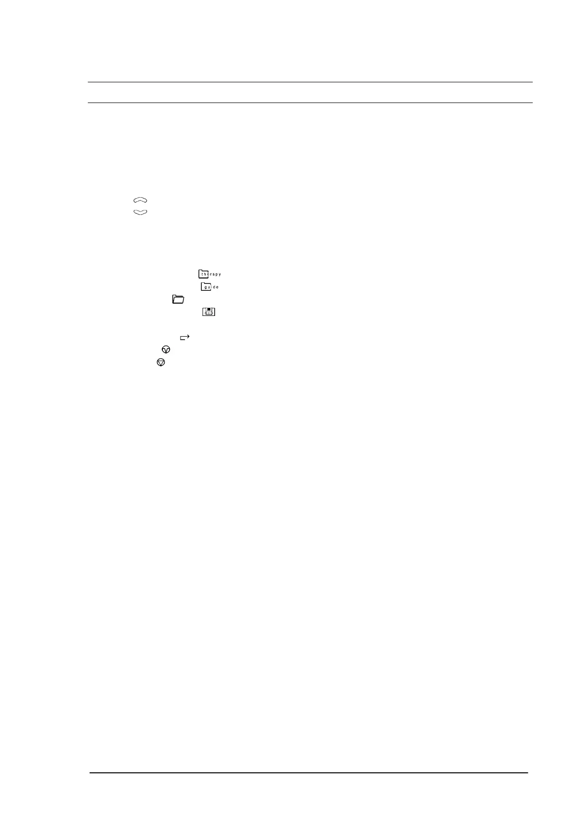
10. Therapy menu key
11.
Guidance menu key
12. Memory key
13.
System settings key
14. Help key ?
15.
‘Go back’ key
16. Pause key
17.
Stop key
18. Output channel A for plate electrodes
19.
Output channel B for plate electrodes
20. Connections for the vacuum electrodes for channel A
21. Connections for the vacuum electrodes for channel B
22.
Yellow pilot lamps, light when the channel concerned can produce current output
23.
Vacuum controller
24.
Stand-by lamp indicating that the appliance is connected to the mains and that the appliance is
turned on
25.
Main switch
26.
Fuse holder
27.
Mains entry
28.
Label with appliance data
29.
Connector to connect to the potential compensating mains
30.
Drain tube of the water reservoir
31.
Vent hole
32.
RS 232 connector for service purposes
33.
Mains switch
34.
Patient cable
35.
Plate electrodes
36.
Vacuum tubes
Phyaction Guidance E/C – service manual version 0.5 Page 8