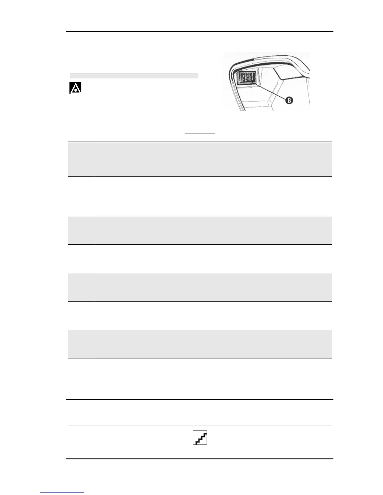
The tables show the position and characteristics
of the fuses on the scooter.
CAUTION
BEFORE REPLACING A BLOWN FUSE, FIND AND SOLVE
THE FAILURE THAT CAUSED IT TO BLOW. NEVER TRY
TO REPLACE THE FUSE WITH ANY OTHER MATERIAL
(E.G., A PIECE OF ELECTRIC WIRE).
FUSE TABLE
Specification Desc./Quantity
1 Fuse No. 1 Position on fuse holder:1
Capacity: 15A
Protected circuits: 12V-180W Socket for electrical
equipment - Helmet compartment light - Electrical saddle
opening - Antitheft device pre-installation
Location:helmet compartment
2 Fuse No. 2 Position on fuse holder: 2
Capacity: 15A
Protected circuits: Radiator electrical fan - Battery re-
charge - Vehicle lights - Power for antitheft device wiring
- Electric fuel pump - Lines protected by fuses 4; 5; 6; 7
and 8
Location:helmet compartment
3 Fuse No. 3 Position on fuse holder: 3
Capacity: 10 A
Protected circuits: High- and low-beam lights - Front
and rear tail lights - License plate bulb
Location:helmet compartment
4 Fuse No. 4 Position on fuse holder: 4
Capacity: 7.5 A
Protected circuits: Power for radio/intercom control
unit pre-installation - Analogue indicator
Location:helmet compartment
5 Fuse No. 5 Position on fuse holder: 5
Capacity: 7.5 A
Protected circuits: Headlight warning light - Front and
rear tail lights - License plate light
Location: front case
6 Fuse No. 6 Position on fuse holder: 6
Capacity: 10 A
Protected circuits: Digital instrument panel - Immobil-
izer LED
Location: front case
7 Fuse No. 7 Position on fuse holder: 7
Capacity: 10 A
Protected circuits: High-beam bulb and warning light in
"passing" - Horn - Power for accessories pre-installation
Location: front case
8 Fuse No. 8 Position on fuse holder: 8
Capacity: 7.5 A
Protected circuits: Stop lights - Vehicle start-up ena-
bling button - Power for radio/intercom control unit pre-
installation and antitheft device installation
Location: front case
Dashboard
instrument panel
X9 Evolution 125 Electrical system
ELE SYS - 77