Functiondescription
OperatingManualPNOZs50
1002194EN02
15
INFORMATION
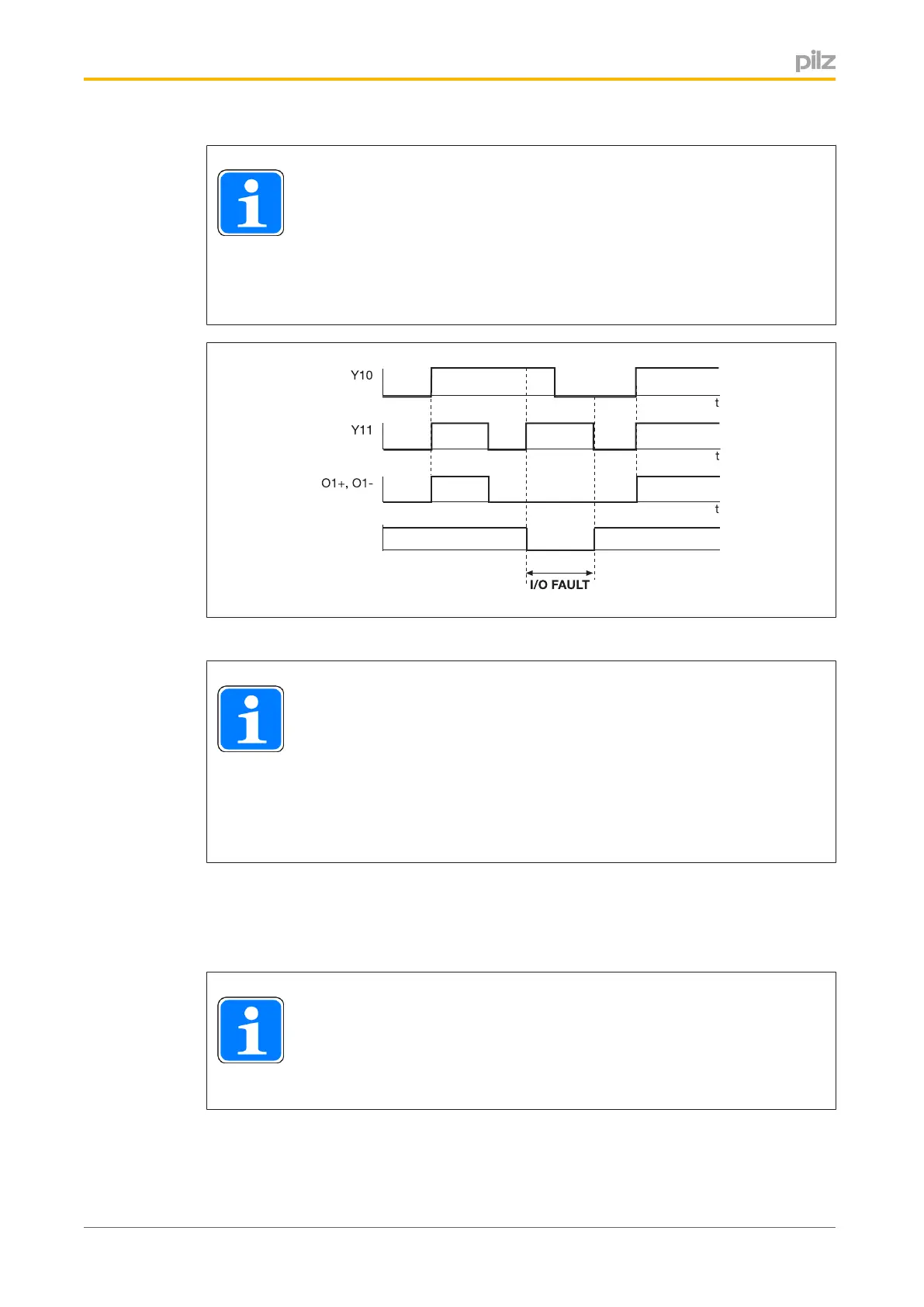
AtthesafeinputsY10andY11/Y20andY21,a"0"signalmustbepresent
beforethecorrespondingoutputO1+/O1/O2+/O2canbeswitchedbya
"1"signalatbothinputs.Ifthisisnotthecase,afaultissignalledandthe
LED"Out1"or"Out2"flashes(thediagrambelowillustratesthis,usingthe
dualpoleinputY10/Y11andtheoutputO1+/O1asanexample).
Fig.:StartupconditionforinputsY10/Y11
INFORMATION
Pleasenote:InputsY10/Y11switchoutputO1+/O1;inputsY20/Y21switch
outputO2+/O2.Intheeventofafault,however,bothoutputswillswitchoff.
StatusoutputsO4/O5alsoswitchoff,irrespectiveoftheswitchstatusofthe
inductiveload.Atthetimeaninput,e.g.Y11,isswitchedon,iftheotherin
put,e.g.Y10,isnotat"0",thefaultsignaloutputO3willsignalafaultviaa
"0"signal.
AftertheoutputO1+/O1and/orO2+/O2isswitchedon,thevoltageU
B1B2
isavailablefora
configurableoverexcitationtimeU
over
.Oncetheoverexcitationtimet
over
haselapsed,the
voltageisreducedthroughpulsewidthmodulation(PWM).Theoverexcitationtimet
over
and
thereducedvoltageU
Avg
areconfiguredviathedisplay.
INFORMATION
Theoverexcitationtimet
over
canalsobeswitchedoffforeachpowercircuit.
Inthiscase,theoutputvoltageofthepowercircuitsO1+/O1and/orO2+/
O2equalsthesupplyvoltageU
B1B2
.

 Loading...


