Function description
Operating Manual PSENmlock mini, PSEN mlm 1 sa 1.1/2.1/2.2
1005802-EN-02-Draft
| 17
} In a fault state, guard locking can be deactivated when die "Lock" LED lights up green. It
cannot be reactivated in the fault state.
Active use of Safety Device Diagnostics
} After activation of guard locking is received from the controller, the safety inputs S31 and
S41 must have a low signal within [t1] max. 500 ms.
Single connection
Guard locking is activated by a low signal at the safety inputs S31 and S41. A high signal at
these safety inputs deactivates guard locking (power to unlock).
Series connection
In a series connection with n safety switches, guard locking is activated by a low signal with
the safety inputs S31/S41 (solenoid activation). Guard locking is activated and safety out-
puts 12/22 are switched on after a delay. Please refer to the technical details (see Tech-
nical details [
63]) for the length of the delay.
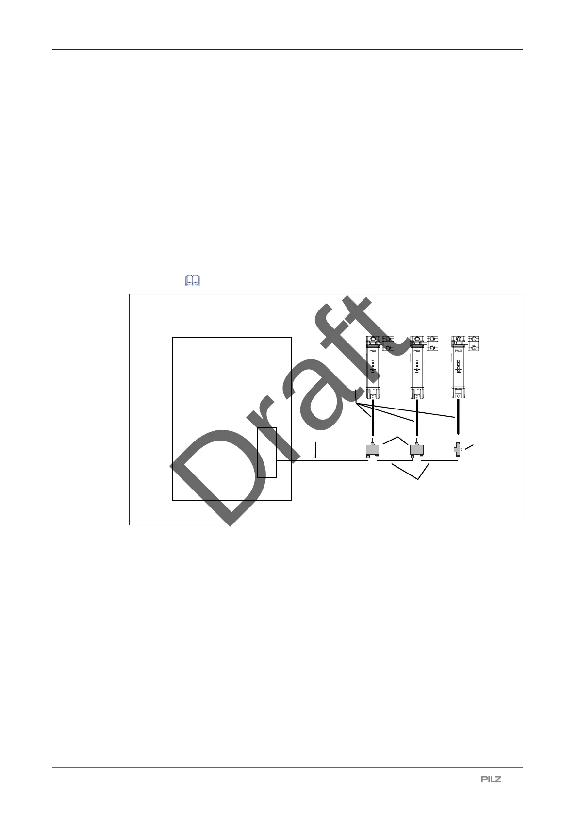
Safety controller
[4]
[3]
[2]
[1]
[5]
Legend
[1] PSEN ml Y junction M12 (order number 570486)
[2] PSEN ml end adapter (order number 570 487)
[3] 12-core cable
PSEN cable M12-12sf M12-12sm (order number depends on the cable length)
[4] 8-core cable
PSEN cable M12-8sf M12-8sm (order number depends on the cable length)
[5] 8-core cable
PSEN cable M12-8sf (order number depends on the cable length)
} Series connection for diagnostics with Safety Device Diagnostics