Function description
Operating Manual PSENmlock mini, PSEN mlm 1 sa 1.1/2.1/2.2
1005802-EN-02-Draft
| 22
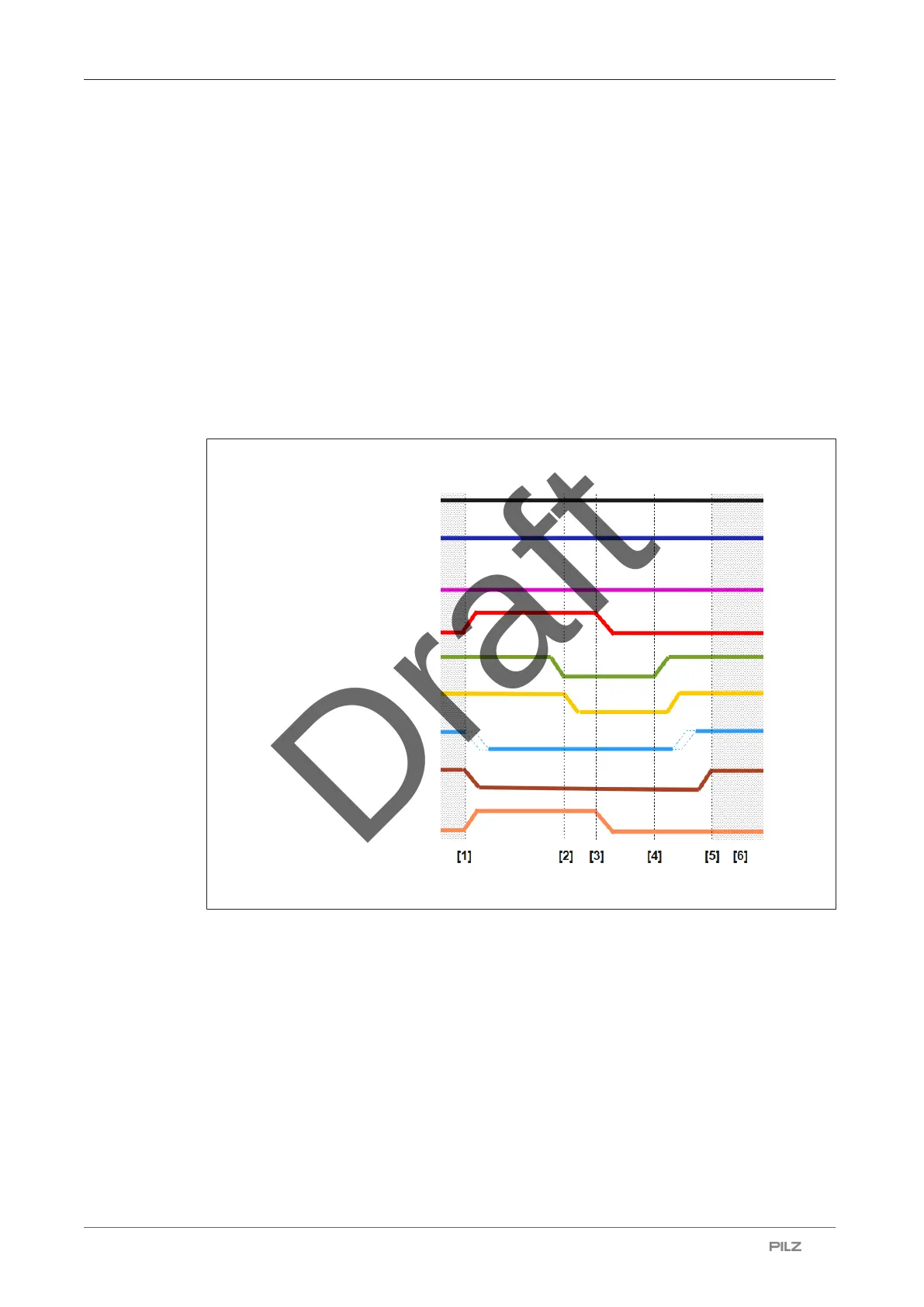
5.8.1.2 Timing diagram, case 2 (automatic guard locking when closing the safety gate)
} The safety gate is closed and is securely locked. The hazardous machine function is ex-
ecuted.
} [1] Guard locking is deactivated via safety inputs S31/S41 (high). Safety outputs 12/22
are deactivated. (low).
} [2] The safety gate is opened, the diagnostic-/signal output Y32 signals that the safety
gate is open (low).
} [3] Guard locking is requested via safety inputs S31/41 (low).
} [4] The safety gate is closed again, the diagnostic-/signal output Y32 signals that the
safety gate is closed (high). Guard locking is activated automatically.
} [5] As soon as guard locking is safely secured, safety outputs 12/22 are activated (high).
} [6] Execution of the hazardous machine function is once again permitted.
Guard locking
Actuator
Y1 (high)
S11/S21 (high)
Auxiliary release (low)
S31/S41
Y32
12/22
32/42
Fig.: Timing diagram, case 2
Legend
[1] Deactivation of guard locking is requested (by safety controller)
[2] Safety gate open
[3] Safety gate guard locking is requested (by safety controller)
[4] Guard locking is activated automatically when closing the gate (power to unlock)
[5] The safety gate is securely locked (guard locking is activated)
[6] Execution of the hazardous machine function is permitted