Wiring
Operating Manual PSENmlock mini, PSEN mlm 1 sa 1.1/2.1/2.2
1005802-EN-02-Draft
| 28
6 Wiring
6.1 Important information
} Information given in the Technical details [
63] must be followed.
} Ensure that the connection cable is disconnected from the power supply when it is
plugged into the safety switch.
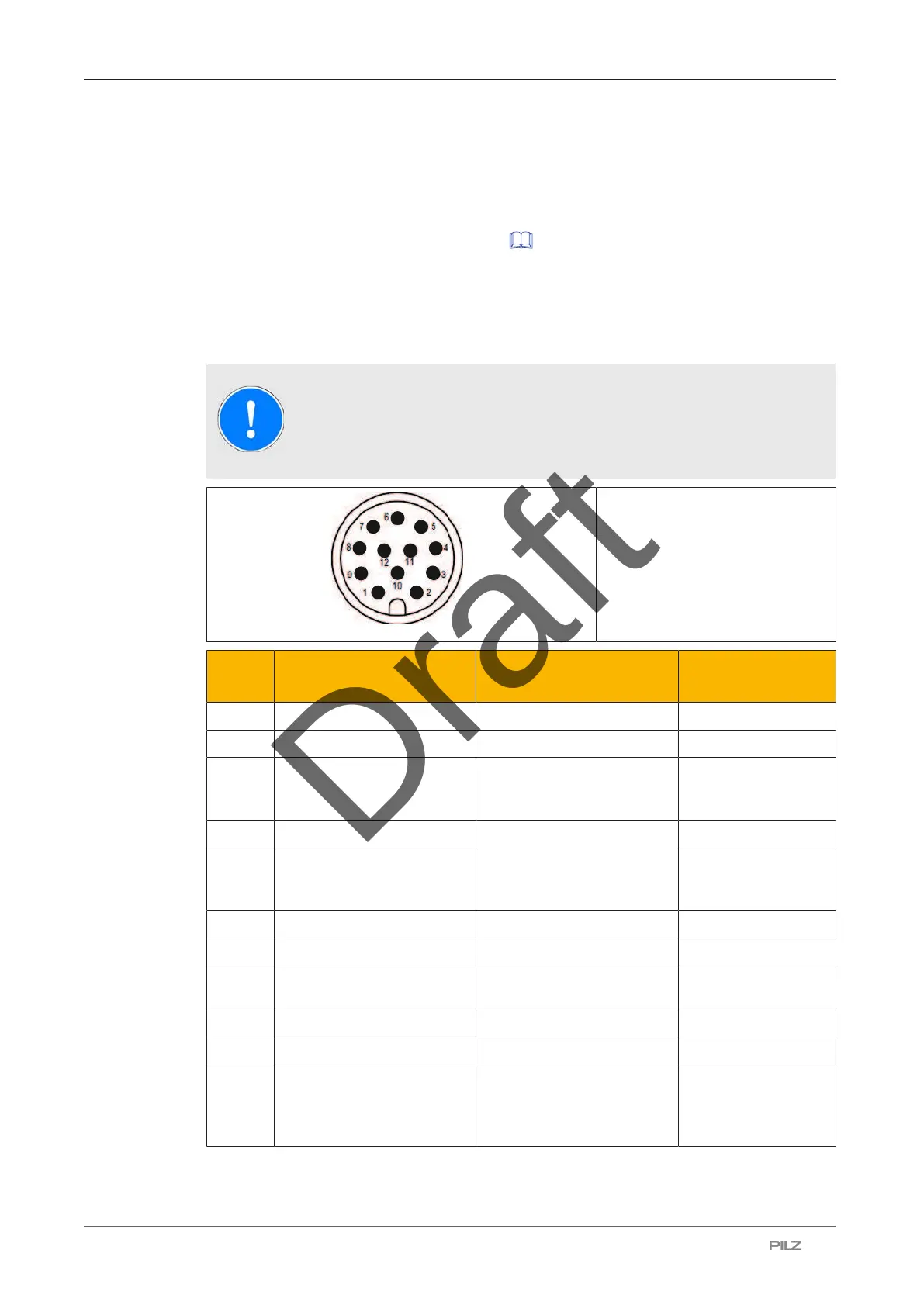
6.2 Pin assignment, connector and cable
NOTICE
The colour marking for the connection lead only applies for the cable that
Pilz supplies as an accessory
12-pin M12 male connector
PIN Function Terminal designation Cable colour (Pilz
cable)
1 +24 V UB A1 Brown
2 0 V UB A2 Blue
3 Operation of solenoid to
open and close guard lock-
ing (channel 2)
S41 White
4 Safety output channel 1 12 Green
5 Operation of solenoid to
open and close guard lock-
ing (channel 1)
S31 Pink
6 Safety output channel 2 22 Yellow
7 Safety input channel 1 S11 Black
8 Signal output/diagnostic
output
Y32 Grey
9 Diagnostics input Y1 Red
10 Safety input channel 2 S21 Purple
11 Operation of solenoid of the
next safety switch in the
series connection (channel
1)
32 Grey-pink