Function description
Operating Manual PSENmlock mini, PSEN mlm 1 sa 1.1/2.1/2.2
1005802-EN-02-Draft
| 15
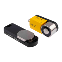
Fig.: Example: Internal attachment of safety switch and actuator b (view from the outside)
Fig.: Example: Internal attachment of safety switch and actuator b (view from the inside)
5.2 Safety outputs 12 and 22
Under these conditions there is a high signal at safety outputs 12 and 22:
} The actuator is detected and
} The guard locking pin has been activated successfully (guard locking pin is in the locked
position) and
} There is a low signal at the safety inputs S31 and S41 and
} There is a high signal at the safety inputs S11 and S21
If one of these conditions is not met, the signal at the safety outputs will be low.
} If one safety input S11 or S21 switches from high to low, while the other safety input re-
mains high, safety outputs 12/22 switch off (low) and the Input LED goes out.
} If this safety input switches back from low to high while the other safety input remains
high, safety outputs 12/22 switch to high.