Function description
Operating Manual PSENmlock mini, PSEN mlm 1 sa 1.1/2.1/2.2
1005802-EN-02-Draft
| 13
5 Function description
5.1 Structure
The interlocking and guard locking system prevents the safety gates to the danger zone
from being opened while there is any hazard within the danger zone (machine movement,
voltage, ...).
The safety outputs 12/22 may have a high or low signal, depending on the position of the
actuator, the state of the safety inputs S31/S41 (solenoid activation) and the state of the
safety inputs S11/S21.
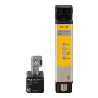
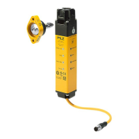
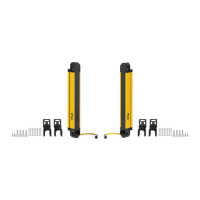
Safety switch and actuator a, external attachment
Legend
[A] Safety switch and actuator a (right-hand side mounting, external attachment)
Gate closed
[B] Safety switch and actuator a (left-hand side mounting, external attachment)
Gate open
[C] Safety switch and actuator a (left-hand side mounting, external attachment)
Gate closed
[D] Actuator a
[E] Safety switch