Connection to control systems and evaluation devices
Operating Manual PSENmlock mini, PSEN mlm 1 sa 1.1/2.1/2.2
1005802-EN-02-Draft
| 32
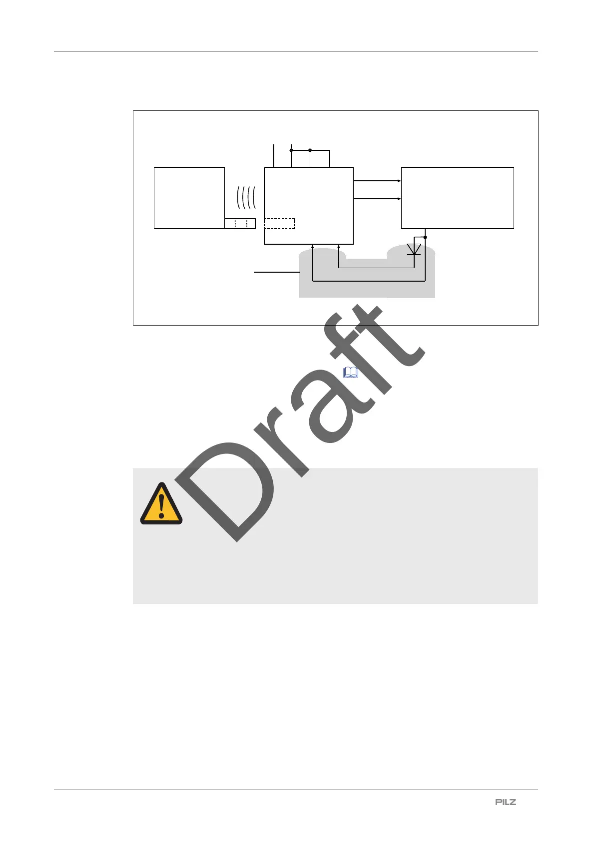
Use in PL d (Cat. 2) applications
PSEN mlm
actuator
PSEN mlm
safety switch
22
S31 S41
12
Lock/Unlock Request
A1
A2
24 V
0 V
S11 S21
[1]
[2]
Activation of guard locking
Safety controller
Legend
[1] Protected cable layout
[2]
Diode optional (see Series connection [
33], "Examples for cable lengths"), to
prevent the reduction of the maximum total cable length.
Use in PL d (Cat. 2) 1-channel:
With a series connection of 4 to 8 safety switches, the total cable length is reduced
by up to 15 m. This reduction can be avoided by installing a diode.
WARNING!
Hazard due to loss of the safety function
Serious or fatal injury could result, depending on the application. Shorts
across the signal cable can cause the safety inputs to activate and lead to
the loss of the safety function.
– Exclude shorts through appropriate measures (e.g. protected cable
layout, see EN ISO 13849-2).
} 1-channel operation for safety inputs S31 and S41 (solenoid operation) via safe outputs
} Use 2-channel processing for safety outputs (12 and 22)
} Use 1-channel operation for interconnected safety inputs S31 and S41 (solenoid activa-
tion)
} Exclusion of shorts across signal cables through appropriate measures (e.g. protected
cable layout, see EN ISO 13849-2)