Connection to control systems and evaluation devices
Operating Manual PSENmlock mini, PSEN mlm 1 sa 1.1/2.1/2.2
1005802-EN-02-Draft
| 34
Up to 8 safety switches can be connected in series.
In practice, the maximum possible number will be limited by the following parameters,
among others:
} The required performance level (e.g. PL d (Cat. 3)),
} The maximum delay or risk time permitted by the application,
} Cable length (see notes on cable lengths),
} Height of supply voltage.
Ensure there is sufficient supply voltage, taking inrush currents and fusing into considera-
tion.
Notes on cable lengths
} The values are determined values under the following conditions:
Room temperature (25°C)
Cable cross section 0.25mm
2
With the output current per output (12,22,Y32), it is presumed that this need only be
supplied by one device. All the others are loaded with the input current from downstream
safety switches, which is already included in the total current.
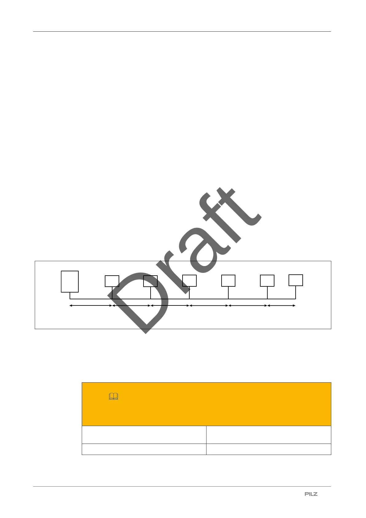
The devices are spread over the total cable length (in this case: an example with 6 safety
switches).
The total cable length is the distance to the furthest device. Stub lines from Y-adapters to
less distant devices are not taken into consideration.
[1]
L1
[2]
[2]
[2]
L2
L3
L4
L5
L6
[2]
[2]
[2]
Legend
[1] Safety controller
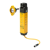
[2] Safety switch PSEN mlm
Examples for cable lengths
Use in PL d (Cat. 3) applications (see Minimum requirements for activation of guard
locking [
31])
2-channel application
Series connection of 1 to 8 safety switches
Supply voltage at the safety controller =
24.0 V
Supply voltage at the safety controller =
28.8 V
Total cable length: 45m Total cable length: 75 m