Connection to control systems and evaluation devices
Operating Manual PSENmlock mini, PSEN mlm 1 sa 1.1/2.1/2.2
1005802-EN-02-Draft
| 37
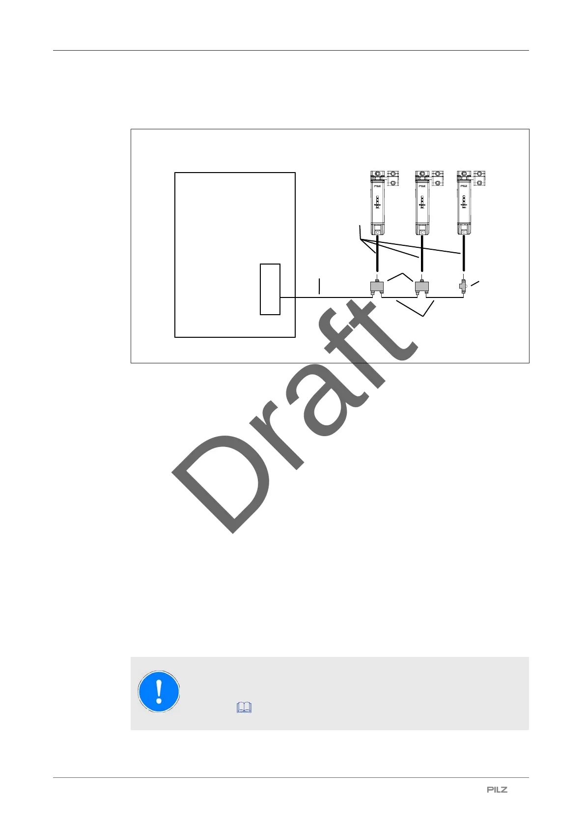
The following options are available for connecting the safety switch in a series connection:
Wiring to the safety controller via PSEN ml Y junction
Safety controller
[4]
[3]
[2]
[1]
[5]
Legend
[1] PSEN ml Y junction M12 (order number 570486)
[2] PSEN ml end adapter (order number 570487)
[3] 12-core cable
PSEN cable M12-12sf M12-12sm (order number depends on the cable length)
[4] 8-core cable
PSEN cable M12-8sf M12-8sm (order number depends on the cable length)
[5] 8-core cable
PSEN cable M12-8sf (order number depends on the cable length)
} When establishing the series connections that connect to the safety controller, use the
following adapters and cables:
– PSEN ml Y junction M12
– PSEN ml end adapter
– PSEN cable M12-12sf M12-12sm
– PSEN cable M12-8sf M12-8sm
} Connection in the control cabinet at the terminal block
– Connect a 12-core cable (for example PSEN cable M12-12sf M12-12sm) to the safety
switch and guide it to the terminal block in the control cabinet.
NOTICE
Before commissioning, check the Series connection of the safety
channels [
59].