12
Controls and Connectors
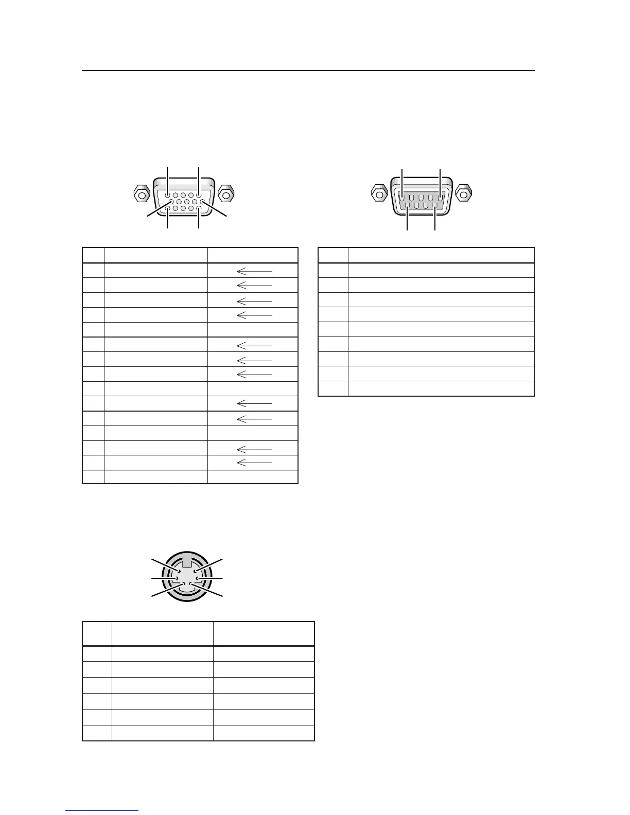
2.4 Pin layout
INPUT 4 (Mini D-sub, 15-pin connector; female)
pin layout
Note : Standard VGA connector (plug and play supported).
Pin No.
Signal
1 NC (not connected)
2 TxD (Transmit Data)
3 RxD (Receive Data)
4 NC (not connected)
5 GND
6 NC (not connected)
7 NC (not connected)
8 RTS (Request To Send)
9 NC (not connected)
Pin No.
Combination Combination
IN OUT
1 GND GND
2 Remote control (input) Remote control (output)
3 TxD (output) RxD (input)
4 NC (not connected) NC (not connected)
5 RxD (input) TxD (output)
6 NC (not connected) NC (not connected)
5
96
1
Combination IN/OUT terminal pin layout
5
3
1
6
4
2
RS-232C terminal (D-sub 9-pin connector; male)
pin layout
Note : Plasma communicates as a DCE derice.
Pin No.
$ INPUT4 input terminals % INPUT4 output terminals
1 R or CR/PR
2 G or Y
3 B or C
B/PB
4 NC (not connected)
5 GND NC (not connected)
6 GND
7 GND
8 GND
9 DDC +5V NC (not connected)
10 GND
11 NC (not connected)
12 DDC SDA NC (not connected)
13 HD or H/V SYNC
14 VD
15 DDC SCL NC (not connected)
1
6
1115
5
10
 Loading...