38
BT37 MarkII: Service Manual MA200606 1.0.0
Component replacement
Fig.5 Removing the plastic rivets
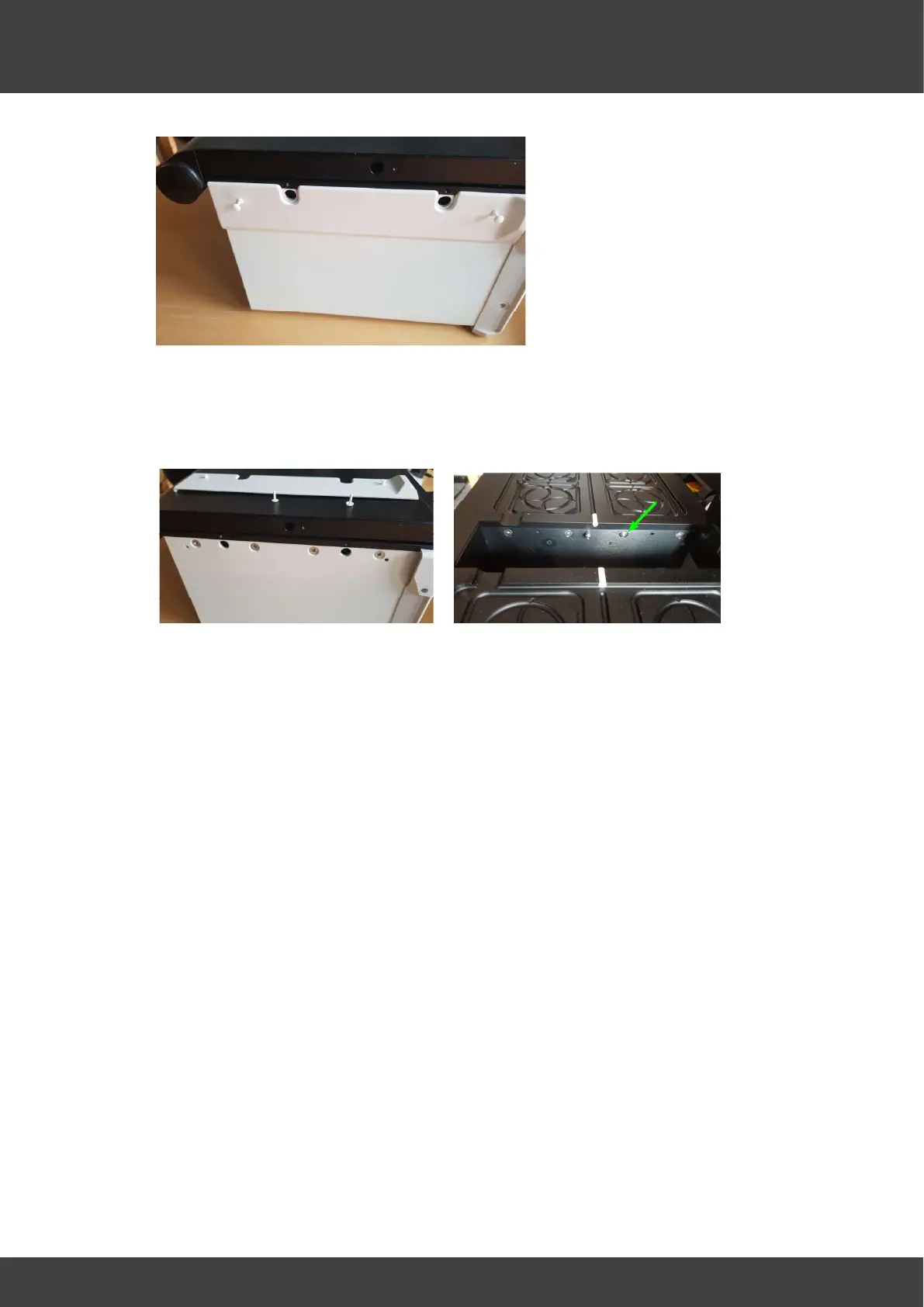
9) Remove the 16 screws that secure the lid assembly to the base as shown in Figures
6 and 7. For each plate there are 4 screws on the outer side of the case, and 4
accessible via the humidifier chamber. Note the 3rd screw from the front of the unit in
the humidifier well for both left and right sides has a domed head, see Fig.7.
Fig.6 Outer lid screws Fig.7 Inner lid screws
Re-assembly of the BT37 incubator
Both left and right top plate assemblies are re-fitted in a similar way.
9) The lids may now be lifted away from the incubator enclosure.
10) Tilt the lid assembly at about 15 degrees to the horizontal and offer it into the top of
the incubator enclosure, so that the edge nearest the humidifier well mates first.
Compress the EMC strips that run along the top edge of the humidifier well with the
lid assembly to allow the opposing edge of the lid assembly to be lowered into the
enclosure.
11) For each lid assembly, refit the 4 pozidrive screws that secure the lid assembly to
the outer wall of the enclosure but do not tighten yet.
12) For each lid assembly, refit the 4 socket head screws that secure the lid assembly
to the humidifier wall but do not tighten yet. The two domed screws fit into the
location third back from the front on each side of the humidifier well.
13) Once all the lid screws are in place gradually tighten them in sequence 1/8 turn at a
time to provide even clamping forces on all screws.
14) Refit the fan by passing the connecting wire around the back of the left humidifier
pcb as shown in Fig.3 and connecting it to the mating FAN connector plug.
15) For each lid assembly refit the two 20-way flat cables to the mating connectors on
the adjacent humidifier board.
16) The flat cable from each top plate connects to the top connector and is orientated so
that the exposed contacts on the cable are towards the rear panel, see Fig.4 for the
right hand plate.
17) The flat cable from each lower plate connects to the lower connector and is
orientated so that the exposed contacts on the cable are away form the rear panel.