43
BT37 MarkII: Service Manual MA200606 1.0.0
Component replacement
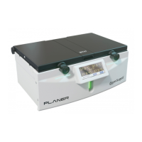
Fig.9
13. Replace the silicone insulating pad and spacers that were removed at step 4
14. Fit the stainless steel protection plate and the 7 countersunk screws that were
removed at step 3.
15. Referring to Hinge adjustment refit the Hinge to the Lid Assembly.
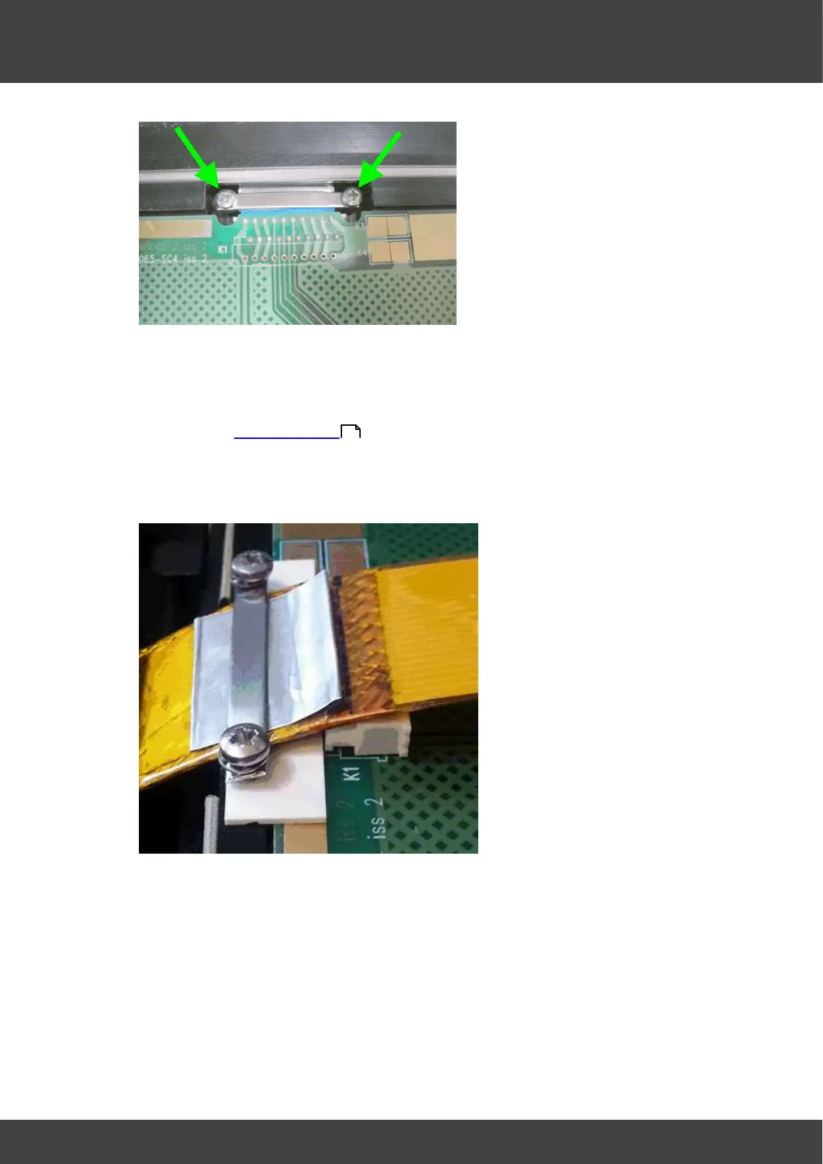
16. Loosely fit metal clamp over cable making sure plastic insulation plate in under
cable, as shown in figure 10.
Fig.10
17. Gently press the ribbon cable using tool former (AM102365) so it is routed to follow
the contour of the hinge and plate. Make sure not to create any sharp bends as
shown in fig.11. Make sure the tinned copper tab is clamped under the clamp and
aligned with mark shown in fig.12. At the same time tighten up both M3 screws.
When removing the tool former you will see a small amount of spring back in the
ribbon cable as shown in fig 14; this is normal. As a second check you can measure
the end of the ribbon cable to the clamp; this should be 143 +/- 1mm (see fig.6).
Readjust if necessary.
82