60
BT37 MarkII: Service Manual MA200606 1.0.0
Component replacement
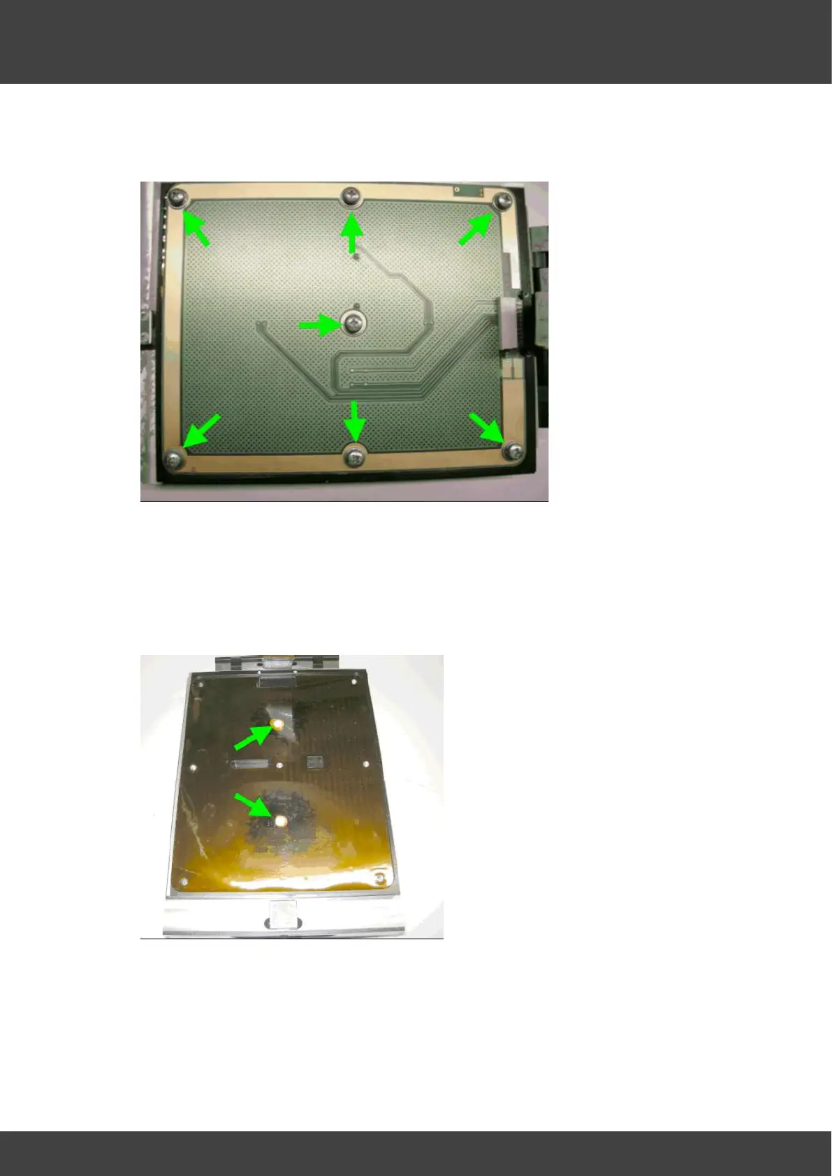
4) Remove the sets of 7 screws and washers that secure the lower heater circuit board
to the lower heater plate. See Fig.3
Fig.3 showing 7 screws securing lower heater circuit board.
4) Carefully remove the old circuit board from the lower heater plate, leaving in position
the insulating kapton sheet that was sandwiched between the circuit board and the
heater plate.
5) Ensure the two recesses in the heater plate that accept the circuit board thermistors
are sufficiently filled with Dow Corning 340 heat sink compound so that the
thermistors will be immersed when the replacement board is fitted, see Fig.4.
Fig.4 showing thermistor wells filled with heat sink compound
6) Gently fit the replacement heater circuit board ensuring the kapton insulating sheet is
still positioned between the circuit board and the lower heater plate, and the two
thermistors remain at right angles to the circuit board as they are slowly immersed
into the heat sink compound.