81
BT37 MarkII: Service Manual MA200606 1.0.0
Component replacement
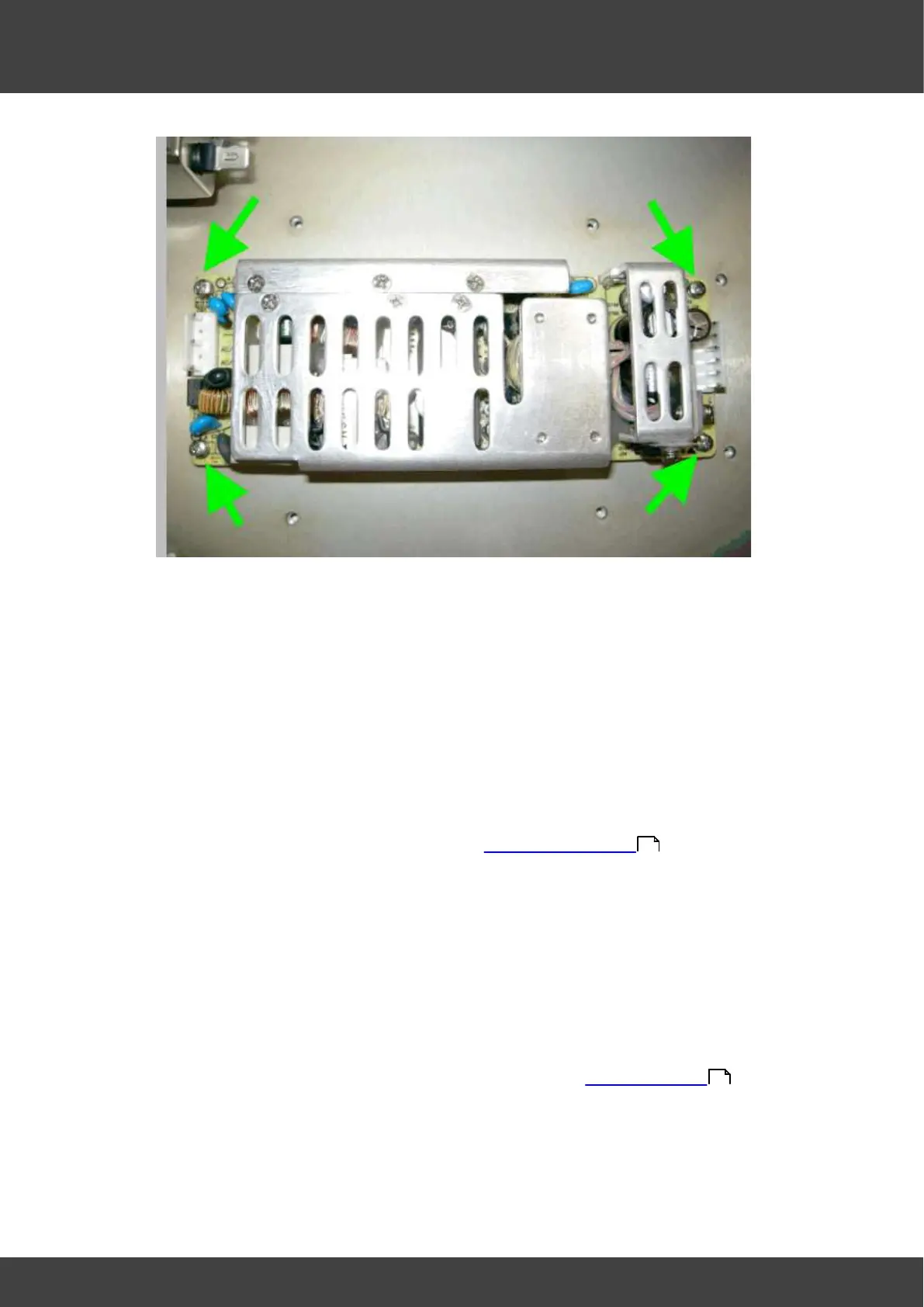
Fig_10 four screws and washers securing power supply
15) Secure the new power supply into position using the screws and washers removed
at step 14
16) Connect the 15V outlet connector and the mains inlet connectors to the power
supply.
17) Place the inner power supply cover into position, whilst sliding the
mains_inlet_grommet and the 15V_outlet_grommet back into place.
18) Secure the inner power supply cover with the screws and washers removed at step
10
19) Refit the outer supply cover and secure it to the inner cover with the screws and
washers removed at step 9
20) Refit the gas valve assembly as described in Gas valve replacement .
21) Refit the front panel assembly using the screws removed at step 6
22) Secure the humidifier assembly by re-tightening the screws loosened at step 5
23) Remove the temporary insulation from the battery terminals. Re-connect the battery
by offering up the spade terminals and reverse_polarity_protection_bar as one
complete unit. It is important to refit the battery connections only when they are held
in position within the reverse_polarity-protection_bar. Never remove the spade
connectors from the bar to fit them individually.
24) Perform an electrical safety earth bond check to both power supply covers using the
Earth Bond Tester, Clare A433R or equivalent.
25) Refit the lids and rear panel of the incubator as described in Opening the BT37 .
26) Perform electrical safety , earth bond and flash tests as described in Planer test
instructions XT101437, XT007800 and XT007801.
51
36