80
BT37 MarkII: Service Manual MA200606 1.0.0
Component replacement
Fig_8 15V loom and grommet
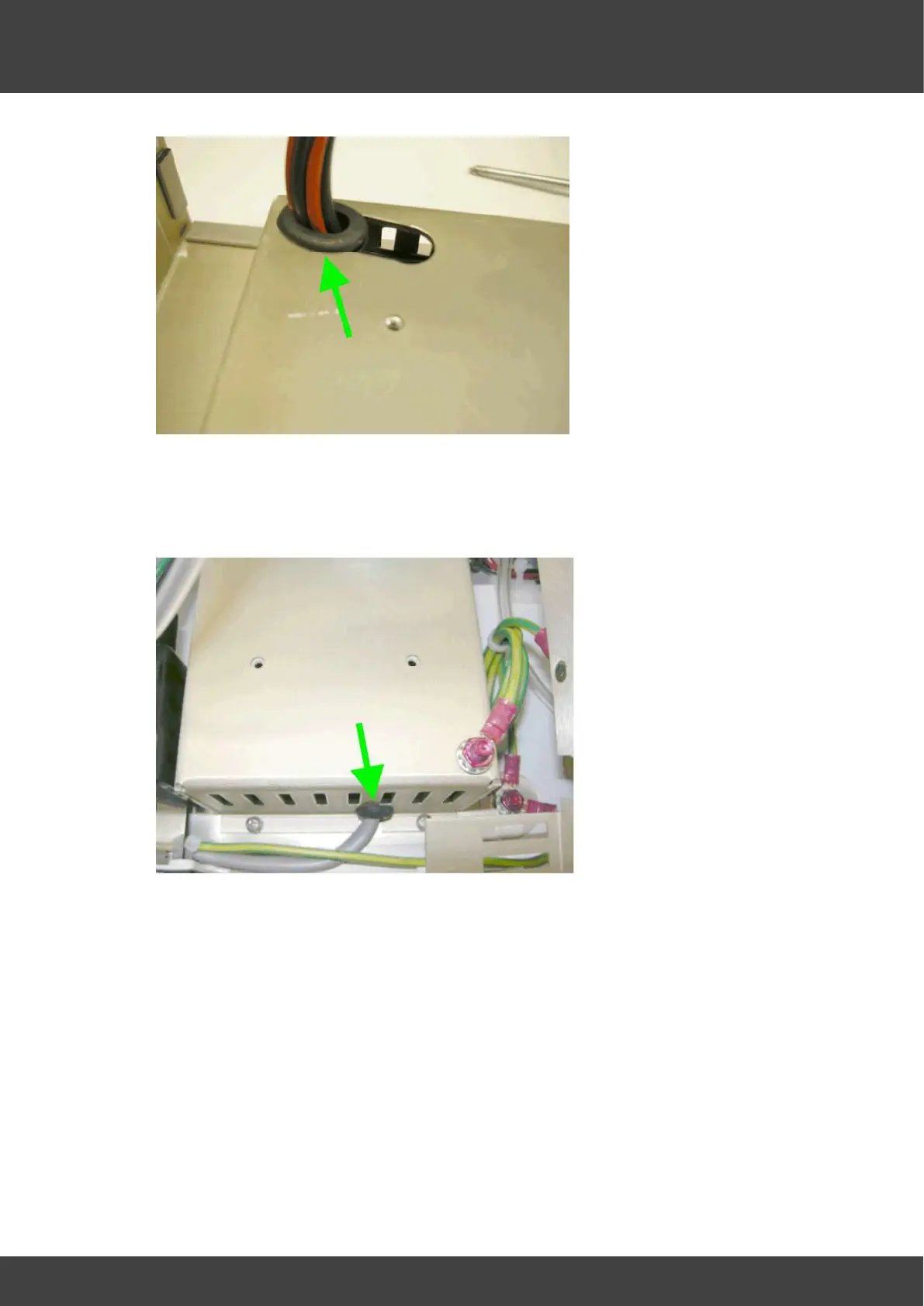
12) Ease the mains_inlet_grommet shown in Fig_9 downwards and out of its slot in the
inner supply cover, and then carefully move the inner cover aside to reveal the power
supply.
Fig_9 mains inlet and grommet
13) Disconnect the mains inlet connector and the 15V outlet connectors from the power
supply.
14 ) Remove the screws and washers ( 4 positions) that secure the power supply to the
enclosure, see Fig_10