79
BT37 MarkII: Service Manual MA200606 1.0.0
Component replacement
Fig_6 screws that secure the outer supply cover
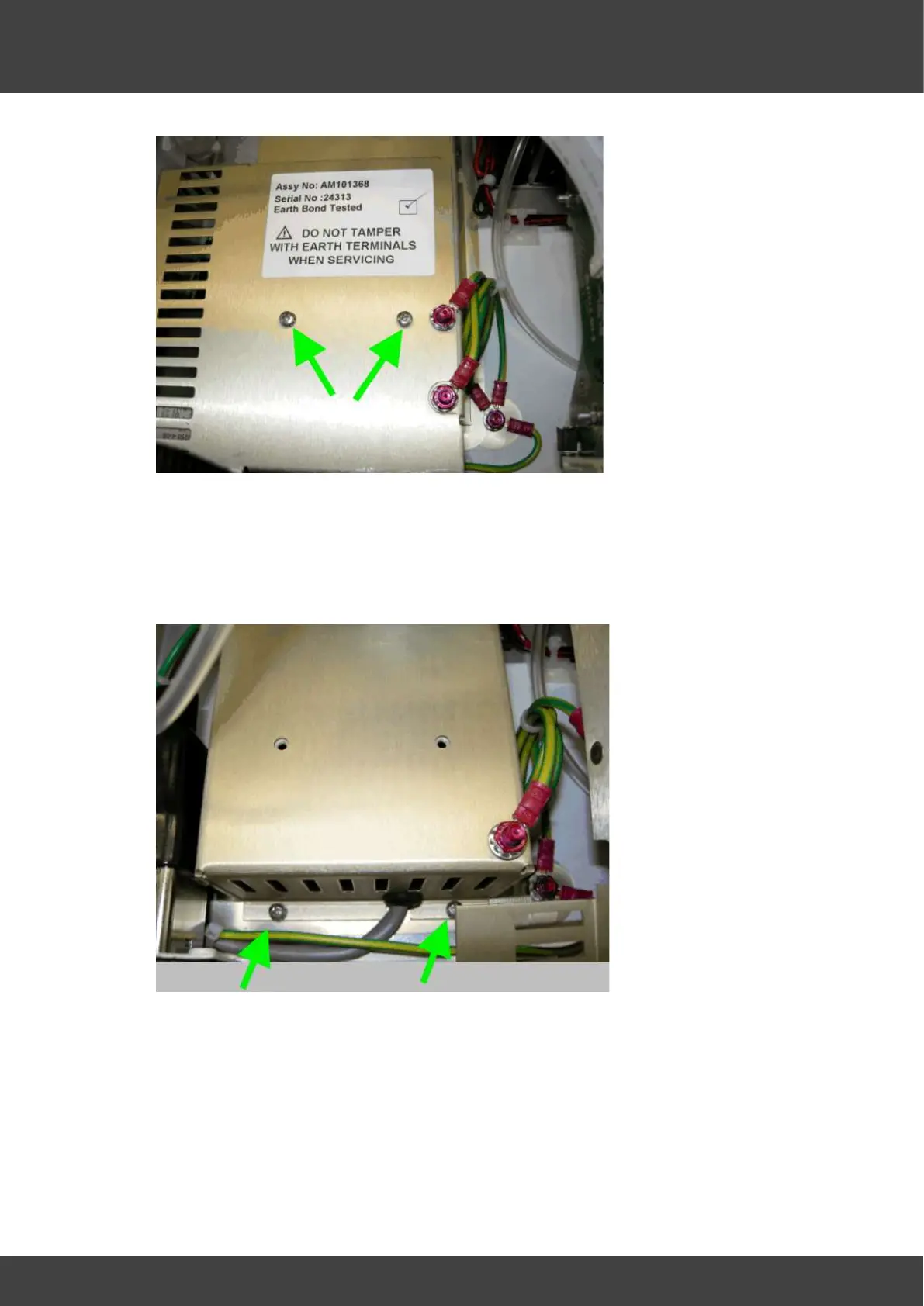
10) Remove the six screws around the bottom edge of the inner power supply cover ( 2
of these screws are shown in Fig_7)
DO NOT UNDO OR TAMPER WITH THE NUTS THAT SECURE THE EARTH
BONDING WIRE TO THE INNER SUPPLY COVER
Fig_7 two of the six screws that secure the inner supply cover
11) Ease the 15V_loom grommet shown in Fig_8 along and out of its slot in the inner
supply cover.