78
BT37 MarkII: Service Manual MA200606 1.0.0
Component replacement
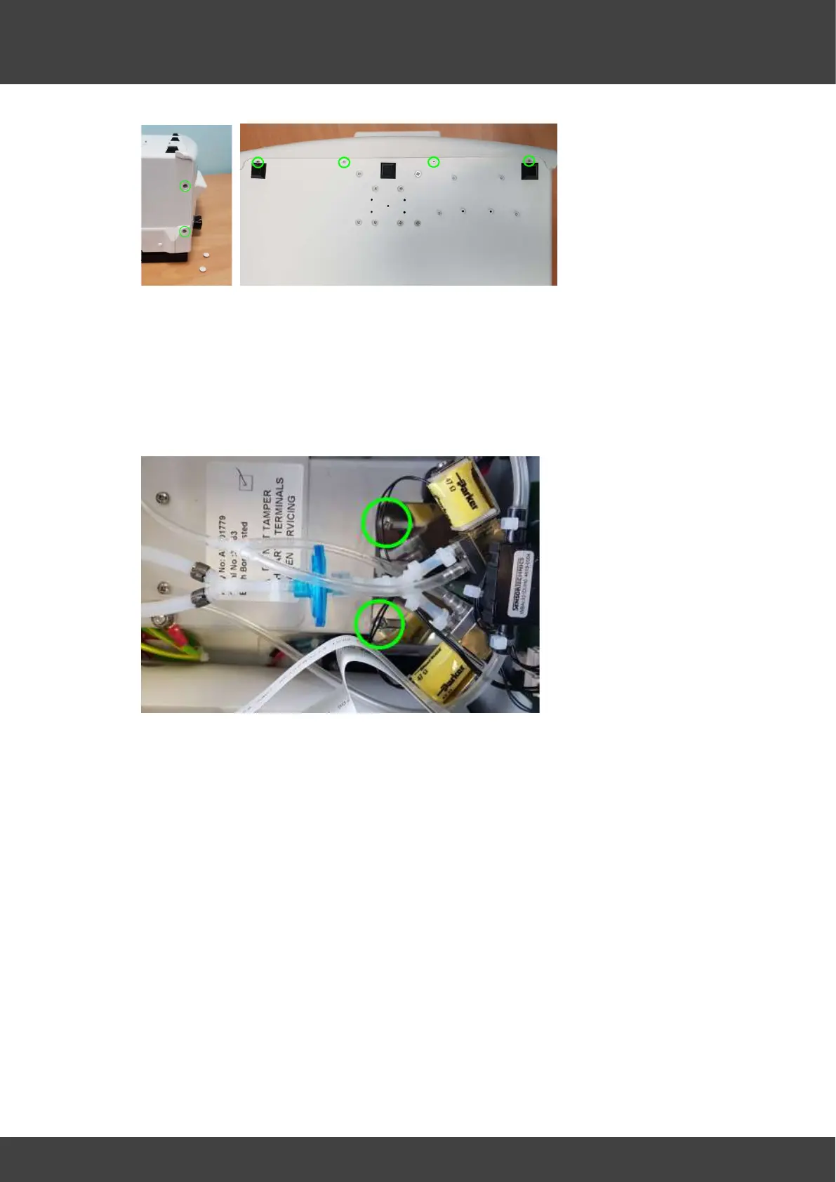
Fig_4 Remove screws along both sides and the base
7) Partially separate the front panel assembly from the case being careful not to stress
any of the attached cables or tubes.
8) Undo the two screws that secure the gas valve mounting bracket to the power supply
enclosure, as indicated in Fig_5, and carefully lift the gas valve bracket and valve
assembly out of the chamber as far as possible to give access to the power supply
covers.
Fig_5 showing the two screws that secure the gas valve bracket.
9) Remove the two screws and washers shown in Fig_6 that secure the outer power
supply cover, and then move the outer cover aside whilst leaving the earth bonding
wire attached.
DO NOT UNDO OR TAMPER WITH THE NUTS THAT SECURE THE EARTH
BONDING WIRE TO THE OUTER SUPPLY COVER