User Manual of VDR-301N
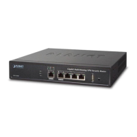
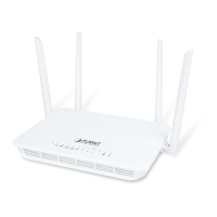
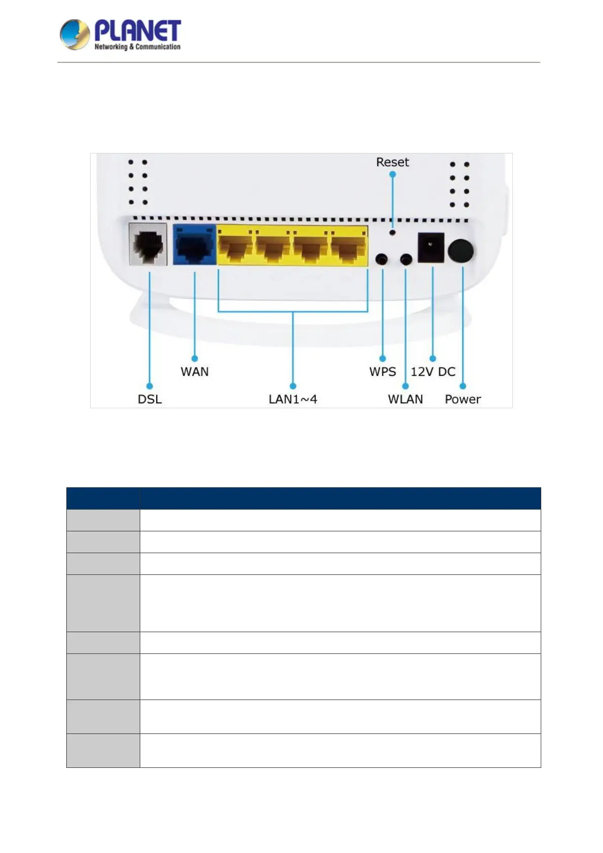
2.1.3 Rear Panel of VDR-301N
The rear panel provides the physical connectors connected to the power adapter and any other network device.
Figure 2-2 shows the rear panel of the VDR-301N.
Figure 0-2 VDR-301N Rear Panel
Rear Panel Port and Button Definition
Connector Description
POWER Power on/off button
12V DC Power connector with 12V DC, 0.5 A
WLAN WLAN switch -- Press for over 3 seconds to enable or disable the WLAN function.
WPS
This button is used for enabling WPS PBC mode.
If WPS is enabled, press this button for over 3 seconds and then the router starts to
accept the negotiation in the PBC mode.
RESET Press for more than 3 seconds to reset to factory default setting.
LAN (1-4)
Router is successfully connected to a device through the corresponding port (1, 2, 3,
or 4). If the LED light is flashing, the router is actively sending or receiving data over
that port.
WAN
The RJ45 WAN port allows data communication between the router and the network
through a UTP cable
DSL
The RJ11 connector allows data communication between the router and the DSL
network through a twisted-pair phone wire