Chapter E - DIMAX3 DIGITAL SYSTEM ADJUSTMENT
E-34 Planmeca Proline CC panoramic x-ray
Technical Manual
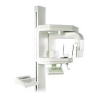
Leave the ball phantom tool in position and place alignment tool adapter to the sensor head.
Place the alignment ruler in position between the primary slot and the sensor alignment tool as
described earlier.
Figure 61
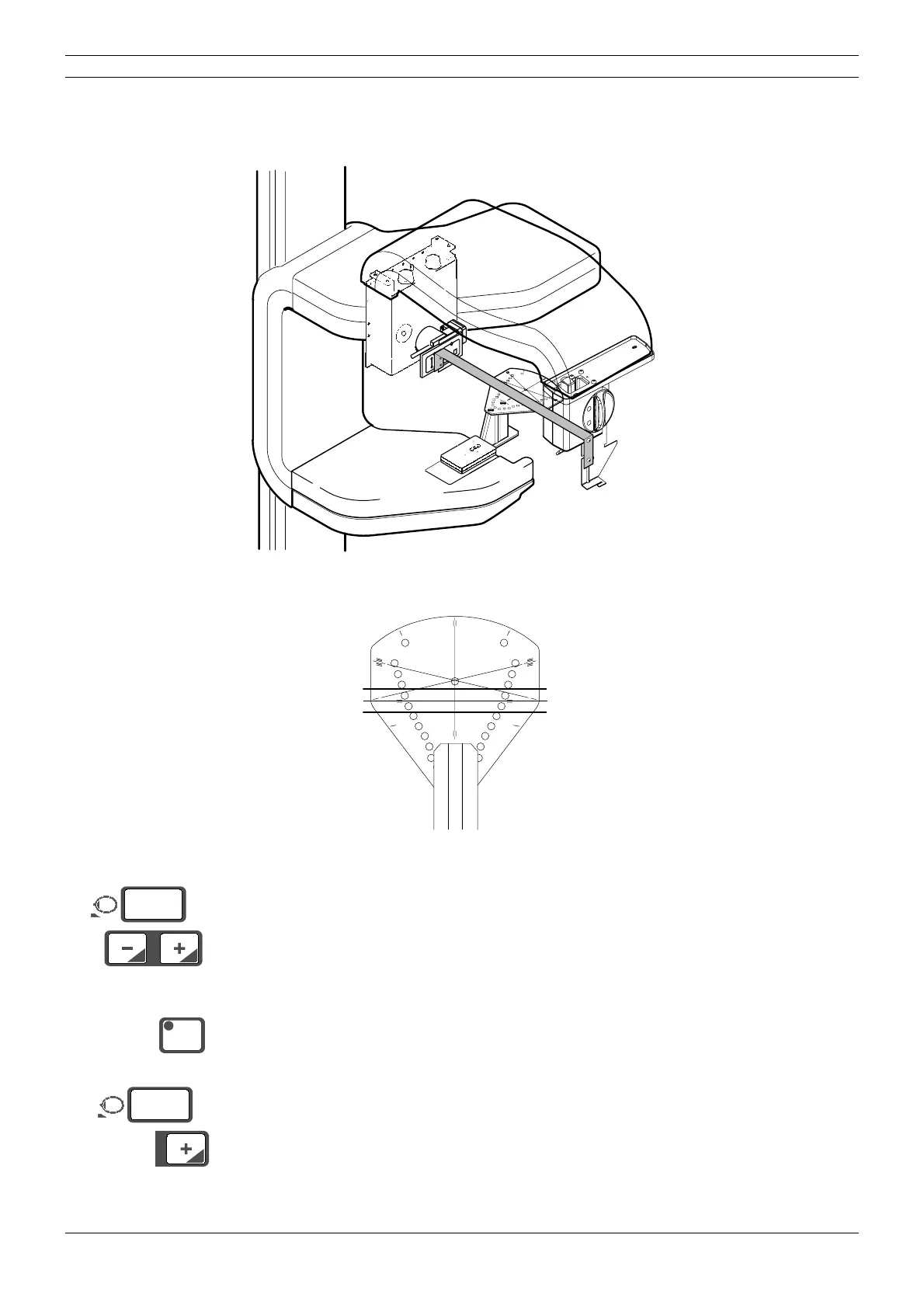
The line on the alignment ruler must line up with the x-line on the ball phantom (Fig. 62).
Figure 62 0° position
Enter the service mode.
Press either of the patient positioning keys once to switch the patient positioning lights on then a
second time to adjust the position of the patient positioning mechanism until the line on the ball
phantom lines up with the line on the alignment ruler. The position of the mechanism will appear
on the display.
Press the CTL-key. The indicator light will come on.
Hold the patient positioning plus (+) key down (about five seconds) until you hear a signal and
the millimeter display zeroes. This indicates that the new position of the patient positioning mech-
anism has been programmed into the memory.
Remove the alignment pin and exit the service mode.
Take another ball phantom picture to check the alignment again. Readjust if necessary.
START
END
PLANM
ECA
No.50971
X-LIN
E
Y-LINE
Dimax2_adj2.eps
START
END
PLANMECA No.50971
X-LINE
Y-LINE
X-LINECA.EPS
Alignment ruler
Ball phantom
Tube head side
Sensor head side
°
mm
12
CTL
°
mm
00