25 November 2011
Replacement
Adjustment
CF-3-13
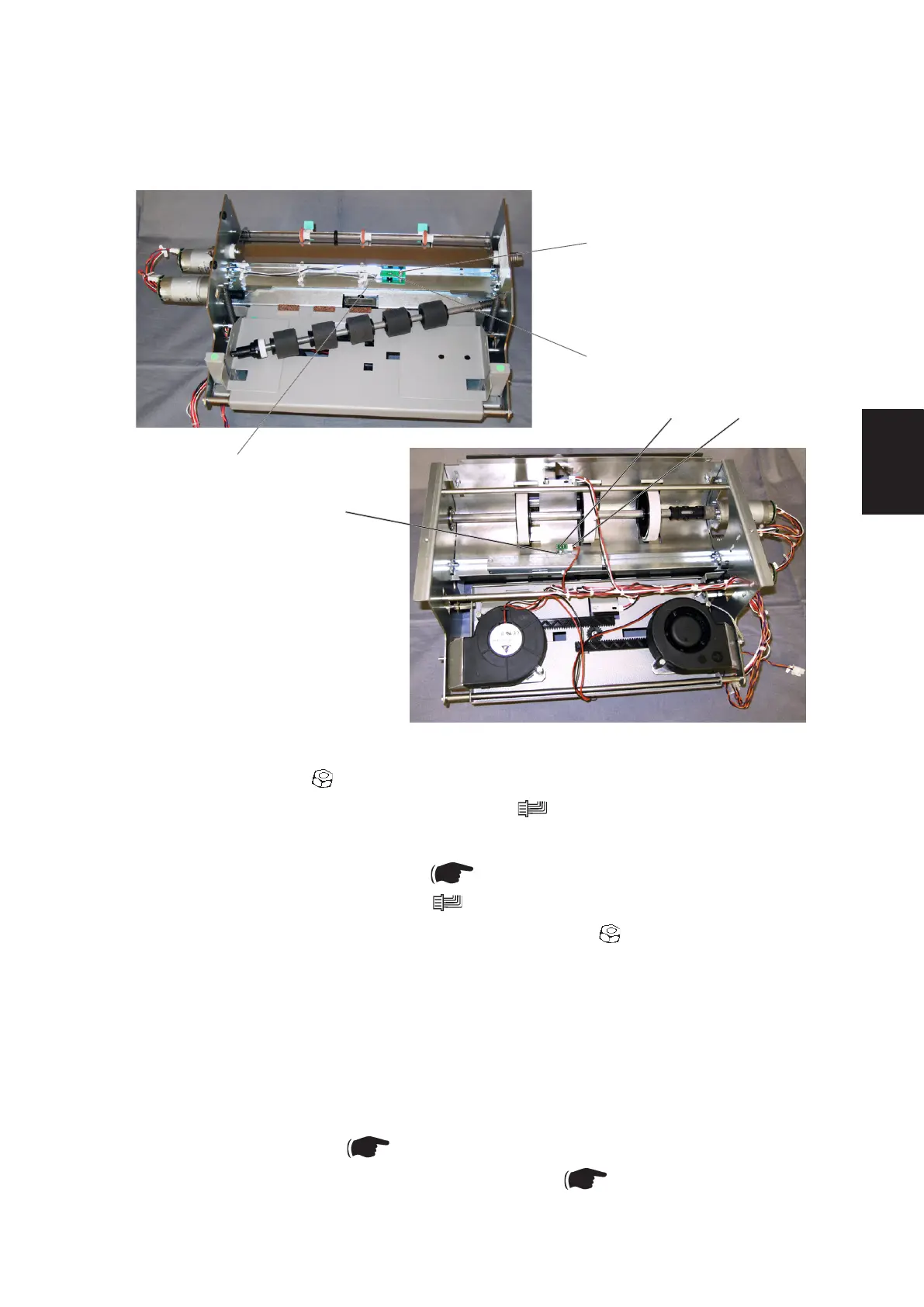
3.2.9 PAPER PATH / DSD DETECTION SENSOR Q30
[E]
[D][F]
[A]
[C]
[B]
Removal
1. Remove nut [A] ( x1).
2. Disconnect Photo transistor connector [B] ( x1).
3. Remove Photo transistor [C].
4. Remove Drive shaft assembly ( 3.2.7).
5. Disconnect LED connector [D] ( x1).
6. Loosen the LED nut [E] and slide off the connector ( x1).
7. Remove LED [F].
Replacement
NOTE: Make sure to install the LED connector [C] correctly, so it will not interfere
with the Drive shaft assembly.
1. Reverse the removal procedure.
2. Enter Service mode ( 5.1.1 in BK5030 Service Manual).
3. Perform Cover Feeder DSD sensor calibration ( 5.5 in BK5030 Service
Manual).
AREA F
 Loading...


