25 November 2011
CF-4-6
FAULT CODE DESCRIPTIONS
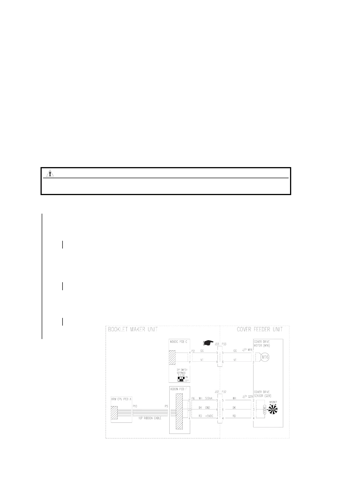
Block schematic diagram to CF-006
CF-006 CF-M16 Cover Drive Motor Pulse Time Out Q29
This Fault Code indicates that the Cover Drive Motor CF-M16 does not receive any encoder pulses
Possible failures:
- Loose cable
- Home position is broken.
- Poor mechanic
- Broken motor/Encoder
Initial Actions
• Enter the Service mode and check Cover Drive motor (M16) in check motors.
• Make sure that plug F P6 on Addon PCB “F” in the Booklet Maker is connected.
• Make sure that jack/plug J32/P32 and J33/P33 in the Cover Feeder is connected.
• Make sure encoder magnet is mounted correctly. Not interfere with hall sensor at PCB. The
distance should be approx. 1mm between magnet and hall sensor on PCB.
Procedure
Enter the Service mode and select sensor Q29 in.
Q29 is toggling between 0 and 1 when rotating the Motor shaft.
Y N
Disconnect plug F.P6 from ADDON PCB “F”.
Measure between J6-4 and J6-22 (5V and GND)
Measure between J6-21 and J6-22 (Signal and GND)
The voltage is 5 VDC +/- 10%.
Y N
Replace ADDON PCB “F”.
Disconnect plug from sensor Q29.
1. Check wire for Continuity / Short circuit from the Red wire at plug Q29 to F.P6-4
2. Check wire for Continuity / Short circuit from the White wire at plug Q29 to F.P6-21
3. Check wire for Continuity / Short circuit from the Black wire at plug Q29 to F.P6-22
Is there Continuity and no short circuit between Red and chassis/GND, White and chassis/GND
Y N
Repair Wire Harness.
Connect plug F.P6 to ADDON PCB “F”.
1. Measure between the Red wire Q29 and the Black wire Q29 (5V and GND).
2. Measure between the White wire Q29 and the Black wire Q29 (Signal and GND).
The voltage is 5 VDC +/- 10%.
Y N
Repair Wire Harness.
1. Replace Motor M16.
2. Replace ADDON PCB “F”.
1. Inside Cover Feeder: Check Q30, Q31, Q32, Q38, M15, M16, M17 and M18 ( BK 5.1).
Check for mechanical bindings, broken, missing or loose parts.
2. Replace motor M16.
WARNING
Switch off the Main Power Switch and disconnect the Main Power Cord
before disconnecting, removing or replacing any electrical components.