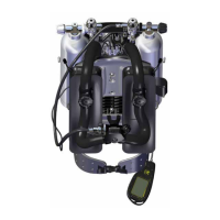
Poseidon SE7EN+ User Manual Appendix 3 Page 107
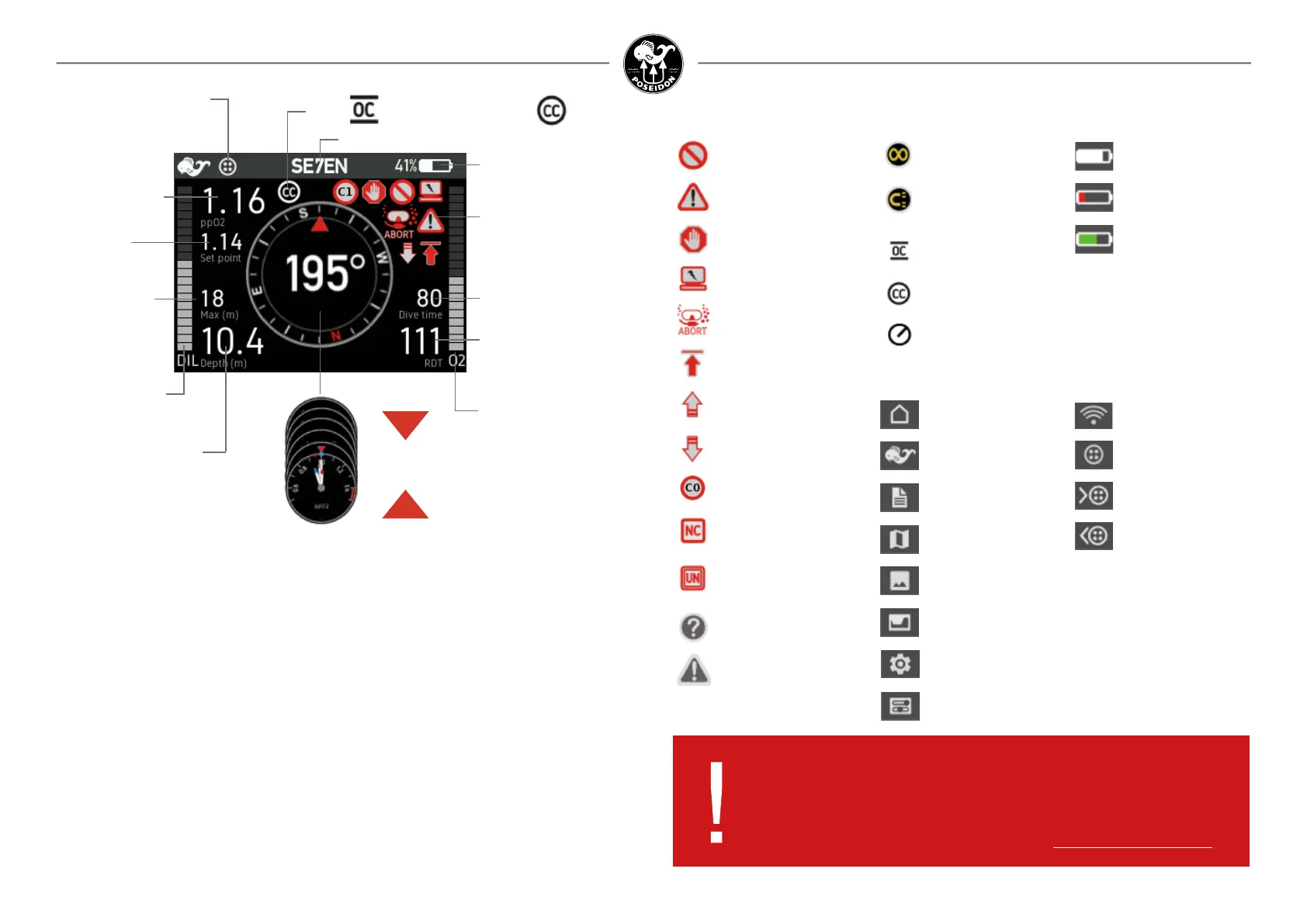
The next most important region is the upper-left part of the screen, where the current PO
2
value
is displayed (2 in gure 3-2). The lower half of the screen includes basic information about depth
(on the left side, 3), and time (on the right side, 4). The left and right edges of the screen (5) include
bar graphs that represent the current capacity of the diluent (left side) and oxygen (right side)
cylinders, as a percentage of total cylinder capacity. Finally, the center circle of the screen (6)
includes several user changeable instruments such as ascent rate, compass and other features.
When the Poseidon SE7EN+ electronics are started the display has the capability of showing many
things but in the gure 3-3 the main symbols, icons and graphical elements are described in detail.
Figure 3-2. M28 display layout.
Figure 3-3. Symbols.
DANGER:
If the Primary Display screen is ever blank while diving the
Poseidon SE7EN+, immediately commence an abort to the surface
in Open-Circuit mode (regardless of whether the HUD Vibrator is
activated). Failure to do so could lead to serious injury or death.
DO NOT DIVE
General alert
Stop ascending
Electronics alert
Abort
Celling alert
Ascend indicator
Decend indicator
C0, C1 or C2 Condence
No Circuit mode
Mouthpiece position
Unknown
Question
Attention
Alarm and Warning symbols
Land view
Dive view
Dive log
Map
Picture
Planner
System
Settings
Display states and views
Level
Level low
Charging
Battery status
Compass calibration
Compass Magnetism
Warning
Open Circuit
Closed Circuit
Gauge Mode
Wi
CAN connected
CAN connected
power input
CAN connected
power output
Open - or Closed-Circuit position
Oxygen
cylinder pressure
Diluent
cylinder
pressure
Center area content
Alarm signal area
Press up or down
button to change
Dive Time
Current Depth
Max Depth
*Setpoint
Remaining Dive
Time or No
Deco Limit
Connection status
Time or current dive mode
M28 battery status
Gas ppO
2
of current
breathing gas
*In SE7EN dive mode the ppO2 of the breathing loop is displayed while in closed circuit
(CC) mode and the ppO2 of the selected OC gas at the current depth is displayed while in
open circuit (OC) mode.
In CPOD dive mode the ppO2 of the breathing loop measured by the connected CPOD is
displayed while in CC mode and the ppO2 of the selected OC gas at the current depth is
displayed while in bailout mode.
In Setpoint dive mode no ppO2 is displayed while in CC mode and the ppO2 of the selected
OC gas at the current depth is displayed while in bailout mode.
In OC dive mode the ppO2 of the selected gas at the current depth is displayed.