Poseidon SE7EN+ User Manual Chapter 1 Page 19
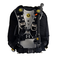
5. Rear CC loop hoses
Breathing loop
All of the components of the breathing loop discussed in this section were rst introduced in
Figures 1-1 and 1-4 above. It is useful to note that all breathing hoses and hose ttings are
identical. There are a total of eight (8) hose connections to be made in the assembly of the
Poseidon SE7EN+. Assembly of these hoses starts at the gas processor, and continues
forward to the mouthpiece.
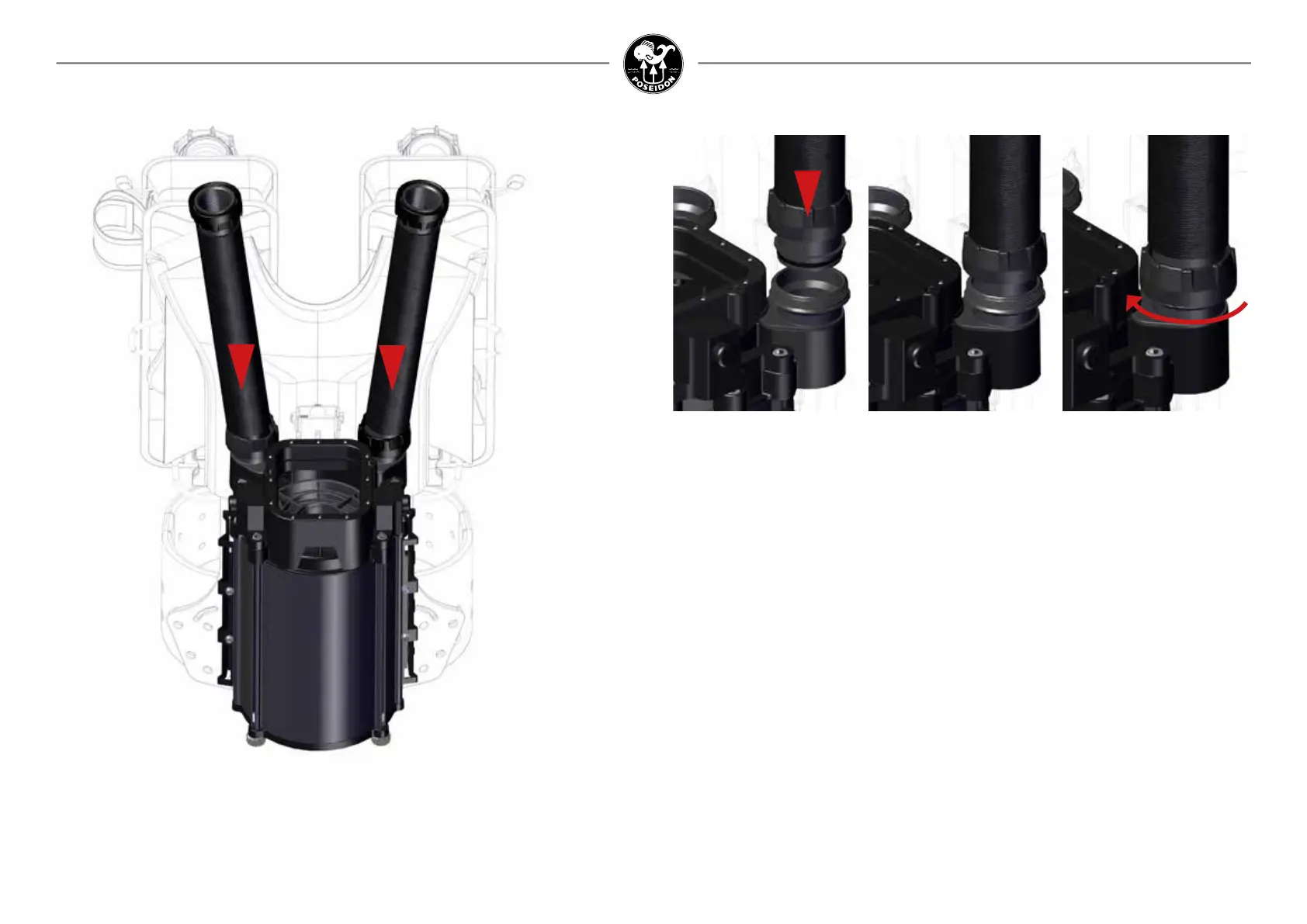
Figure 1-27.
Insert the rear left and right hose
into the gas processing house.
Figure 1-29.
Push hose connector into
receiver until outer ange is
ush with start of threads.
Figure 1-30.
Hand tighten the swivel
capture nut: Do NOT use
tools or over-tighten.
Figure 1-28.
Closeup of hose connection.
First, select two hoses to be used as the rear left and right breathing hoses (Figure 1-27). Insert
the end of one of the hoses into the left (inhalation) threaded breathing manifold (Figures 1-28
and 1-29). Pay particular attention to the condition of the radial o-ring on the end of the hose
and to the radial sealing surface inside the lip of the threaded breathing manifold. The o-ring,
o-ring groove, and sealing surface at the hose junction must all be clean and free of all debris;
free of scratches and gouges; and properly lubricated before assembly. Be sure when inserting
the hose end into the threaded breathing manifold that the radial o-ring does not extrude from
its circular groove. The radial o-ring in the hose end should insert smoothly into the radial
sealing surface (Figure 1-28) until it is no longer visible and the top rim of the hose end is ush
with the ledge just above the threads on the manifold (see Figure 1-29).
Once the hose tting is properly inserted (Figure 1-29), slide down and hand-tighten the hose
swivel nut (Figure 1-30). Make sure that the threads are properly engaged and are not cross-
threaded. The ttings are designed for ease of assembly, and the capture nut should freely
rotate until the nut locks against the lower thread ange on the manifold. Do NOT over-tighten
or use any tools, as this may result in stripping the threads and ruining both the connector and
the manifold port.
Repeat these steps with the right rear breathing hose, so the rig is as shown in Figure 1-27.