Poseidon SE7EN+ User Manual Chapter 1 Page 22
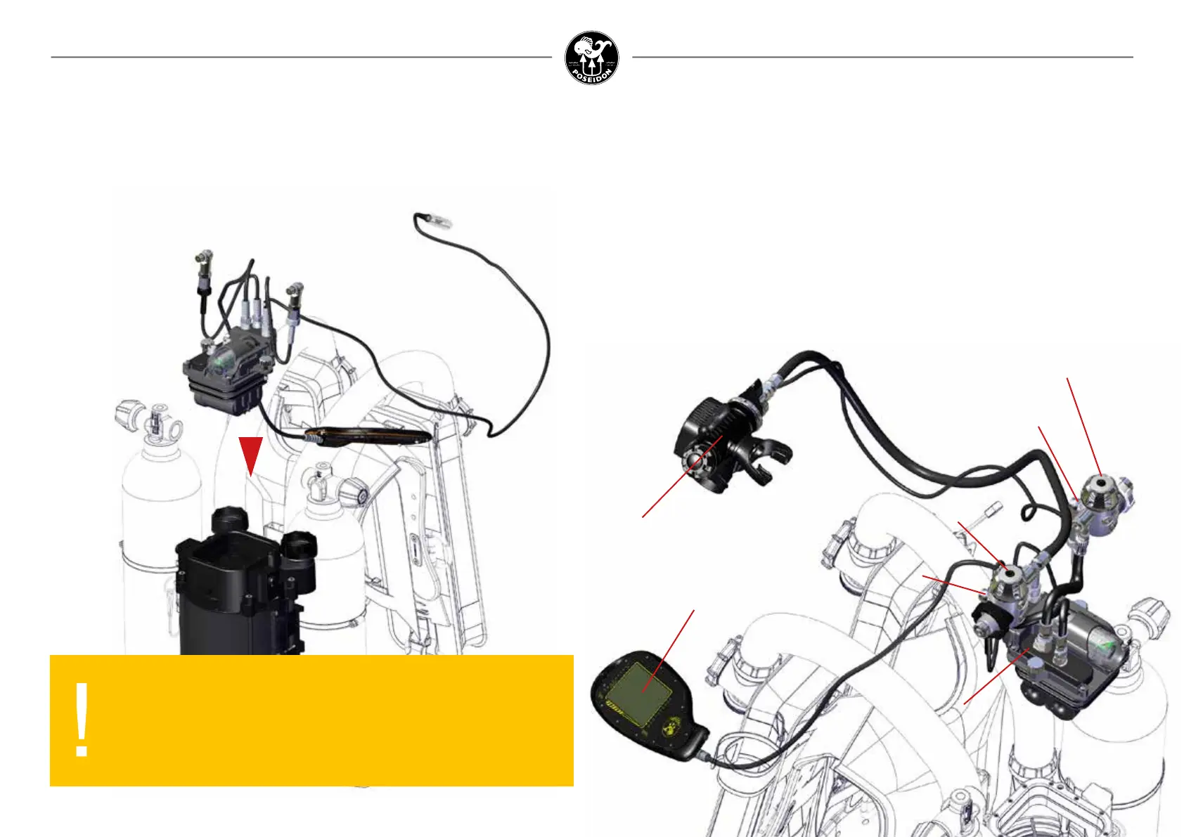
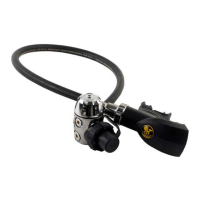
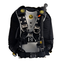
Oxygen regulator
Diluent regulator
Oxygen cylinder
high pressure sensor
Diluent cylinder
high pressure sensor
Electronics module
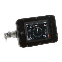
Primary display
Mouthpiece
Figure 1-35. Inspect the Electronics Module and Related Components.
7. E-module
Check and make sure that the two o-rigs around the e-module are in place and without
damage.
Align the e-module so that the cable junkction box point in the direction of the two canister
housing top breathing loop interface.
Gently push the e-module in place and tighten the two
screws, securing the e-module.
At the heart of the Poseidon SE7EN+ is an electronic, pneumatic, control, and user feedback
system. The electronics module, shown at the center of Figure 1-35, contains the primary
backpack computer system, the smart battery, and the pneumatics control block assembled
in one compact plug-and-play block.
The electronics module contains its own processor, connected via a network to the processors
in the primary display, battery module, and the HUD (head-up display) in the mouthpiece.
Pneumatic connections to the oxygen and diluent regulators allow for PO
2
control and oxygen
sensor calibration and validation. This entire electronics system comes pre-assembled from
Poseidon when you purchase the Poseidon SE7EN+. Several of these sub-systems will be
discussed in detail later.
To begin assembly of the electronics module into the gas processor backpack, set the car-
tridge housing upright and on a solid at base as shown in Figure 1-35.
WARNING:
Cables should always be connected to the e-module.
Connectors to display, hud and sensors are only meant to be
disassembled for maintenance and replacement purposes by a
trained service technician.